Hi all,
In an effort to liven up this community, I'll post this project I'm working on.
I'm building a solar hot water controller for my house. The collector is on the roof of a three-storey building, it is linked to a storage tank on the ground floor. A circulating pump passes water from the tank to the collectors and back again when a temperature sensor on the outlet of the collector registers a warm enough temperature.
The current controller does not understand that there is 15 metres of copper piping to pump water through and cycles the circulating pump in short bursts, resulting in the hot water at the collector cooling considerably by the time it reaches the tank (even though the pipes are insulated). The goal of my project is to read the sensor and drive the pump in a way to minimise these heat losses. Basically instead of trying to maintain a consistent collector output temp with slow constant pulsed operation of the pump, I'll first try pumping the entire volume of moderately hot water from the top half of the collector in one go back to the tank and then waiting until the temperature rises again.
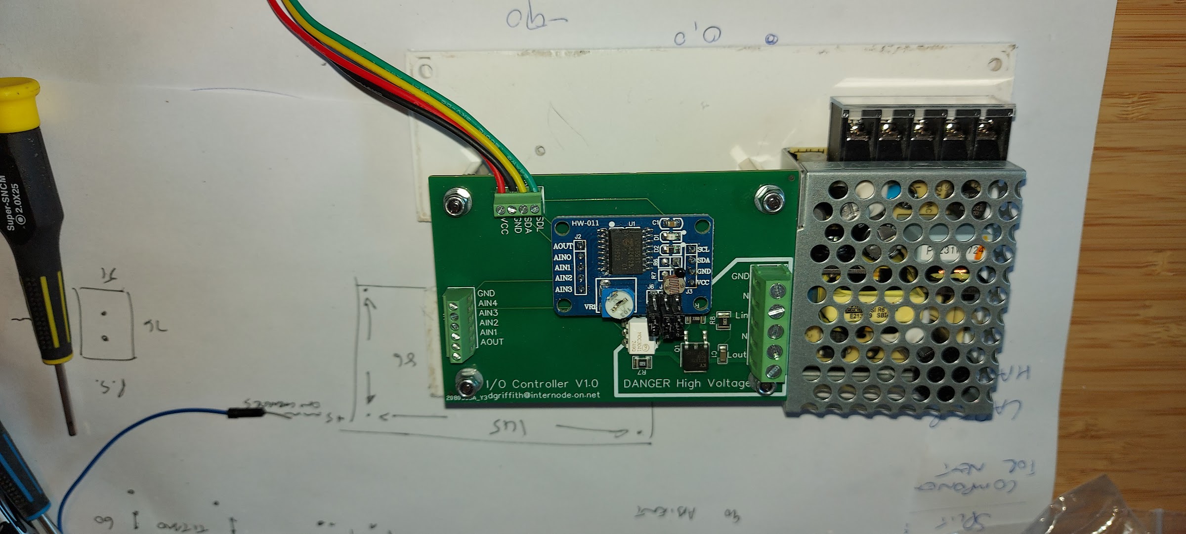
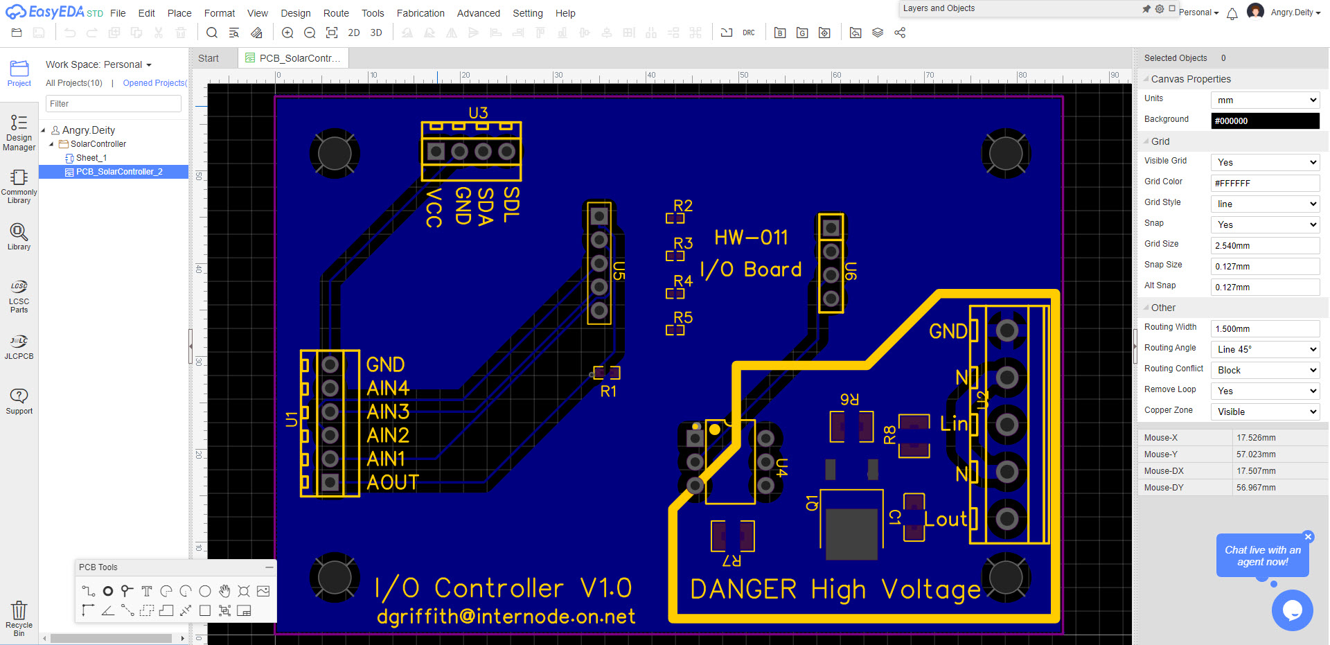
I am using an Adafruit PyPortal Titano as the controller, running circuitpython. For I/O I am using a generic ebay PCF8591 board, which provides 4 analog input and a single analog output over an I2C bus. This is inserted into a motherboard that provides pullup resistors for the analog inputs and an optocoupled zero crossing SCR driver + SCR to drive the (thankfully low power) circulating pump. Board design is my own, design is rather critical as mains supply in my country is 240V.
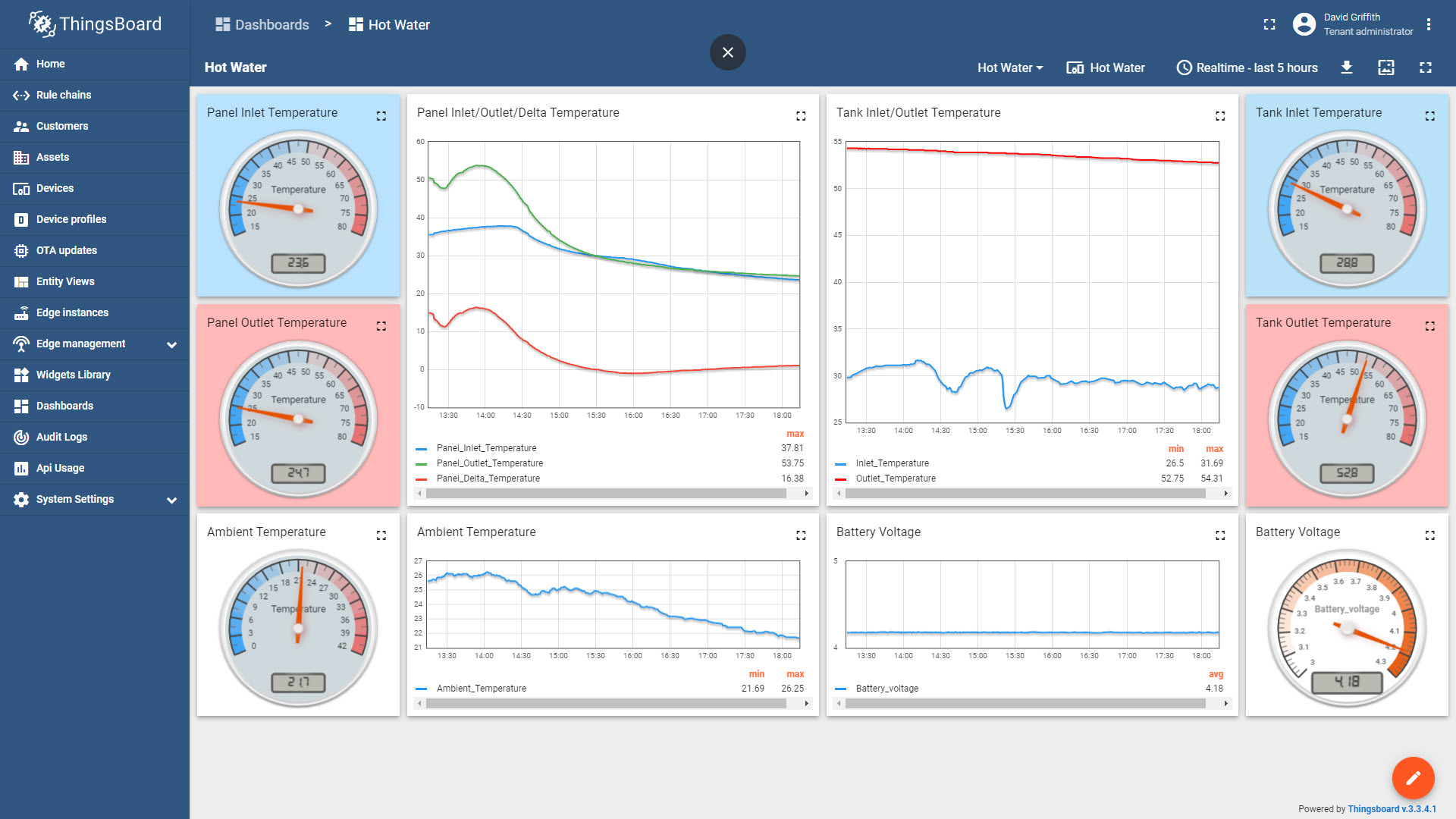
The original sensors are simple NTC thermistors, one at the bottom of the tank, and one at the top of the collector. I have also added 4 other Dallas 1-wire sensors to measure temperatures at the top of tank, ambient, tank inlet and collector pump inlet which is 1/3rd of the way up the tank. I have a duplicate of the onewire sensors already on the hot water tank using a different adafruit board and circuitpython. Their readings are currently uploaded to my own IOT server and I can plot the current system's performance, and I intend to do the same thing with this board.
The current performance is fairly dismal, a very small bump of perhaps 0.5 - 1 deg C in the normally 55 degree C tank temperature around 12pm to 1pm, and this is in Australia in hot spring weather of 28-32 degrees C.(There's some inaccuracy of the tank temperatures, the sensors aren't really bonded to the tank in any meaningful way, so tank temp is probably a little warmer than this. But I'm looking for relative temperature increases anyway)
Right now , the hardware is all together and functional, and is driving a 13W LED downlight as a test, and I can read the onewire temp sensors, read an analog voltage on the PCF8591 board (which will go to the NTC sensors), and I'm pulsing the pump output proportionally from 0-100 percent drive on a 30 second duty cycle, so that a pump drive function can simply say "run the pump at 70 percent" and you'll get 21 seconds on, 9 seconds off. Duty cycle time is adjustable, so I might lower it a bit to 15 or 10 seconds.
The next step is to try it on the circulating pump (which is quite an inductive load, even if it is only 20 watts), and start working on an algorithm that reads the sensors and maximises water temperature back to the tank. There are a few safety features that I'll put in there, such as a "fault mode" to drive the pump at a fixed rate if there is a sensor failure, and a "night cool" mode if the hot water tank is severely over temperature to circulate hot water to the collector at night to cool it. There are the usual overtemp/overpressure relief valves in the system already.
All this is going in a case with a clear hinged cover on the front so I can open it and poke the Titano's touchscreen to do some things.
Right now I am away from home from work, so my replies might be a bit sporadic, but I'll try to get back to any questions soon-ish.
A few photos for your viewing pleasure:
The I/O and mainboard plus a 5V power supply mounted up:

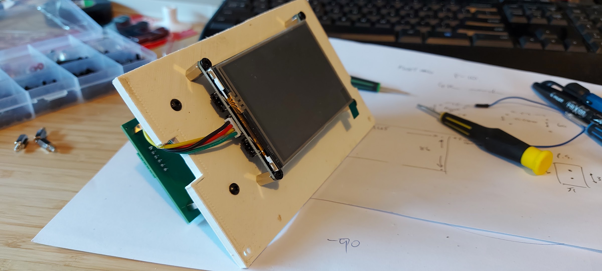
The front of the panel, showing the Pyportal:

Thingsboard display showing readings from the current system:

Mainboard PCB design and construction via EasyEDA:


Yeah, that seems like a good way to go. 65 degrees at ground level is what I'd also expect. My assumption up top would be close to 90/95 degrees. Driving the pump more often would be interesting.