It's a shame, but unsurprising. Especially with everyone addicted to live service skinner boxes now and a certain someone insisting live services would cease to exist overnight if this went anywhere.
Heavybell
joined 2 years ago
Okay, now build a gigantic coal furnace in the middle before the storm comes.
Would make a better rhyme if you made it "The USA just bombed Iran, paint all the green ones back to tan." 'Cause then the syllable count matches.
Perhaps they're hoping to stop people from going to linux for gaming. PC gaming has certainly not hurt their stranglehold on the top OS spot.
Well I also stopped playing most AAA games a while ago, which is where you see console lead platform the most, so yeah I don't have a newer example sorry. They may or may not exist, I wouldn't know.
Ohh! Nice to know! Might try that with War Thunder tomorrow. No clue if that's SDL or not.
It's always preferable to have options, yeah. I so far haven't found a need to use an xorg session, knock wood.
Glad that's working out for you. :)
BTW wine vanilla and some custom proton builds are adding direct wayland support, just so you know. It's still experimental but works great for some games, just in case you have others tying you to X.
Everything huh? I'll believe that when I see it. :P I've been waiting on Bloodborne and the Demon's Souls remaster for so long.
I also don't completely agree console targeted games are a good thing. Sure, controller standardisation has been great for games played on a controller, but if you have any other type of peripheral, that thing is still using DirectInput, with all the associated issues. Plus I'm sure Mass Effect 2 wasn't the only game that was less than it could have been for being console first.
And yeah, a lot of older PC games were targeted at hypothetical future computers. In many cases that worked out; you could play it on medium now, and play it on high on your newer PC in future years (which maybe it's just because I was younger and had less money, or maybe it's because the games industry has expanded since then, or a bit of bother, but I feel like that was more a thing in the past than often happens now). There were also cases where it didn't work out, of course. Notably Crysis, which was coded assuming CPUs would continue their meteoric rise in single core clock speed, which basically stopped being a thing the day it came out. Meaning PCs today still can't run it that well.
What was I saying? Eh nevermind.
Not sure I agree on the "better news". I'd love if they gave up on making consoles and put more stuff on PC, tho if they pivoted to cloud only that would indeed be the worst outcome. :P
That said, sure, the ideal outcome would be PS6 and releasing games on PC. I don't want a new console but I respect people who do.
Just lower case "yank" will suffice. That one's already in use.
cross-posted from: https://lemmy.world/post/15565311
It was a long running project, but I finally did it. I built what I'm calling a smart mailbox that communicates the presence of mail locally with Home Assistant via ESPHome.
Parts:
- Pine plank roughly the width of my mailbox
- Treated pine plank for mounting
- Thin sheet of perspex or similar transparent plastic
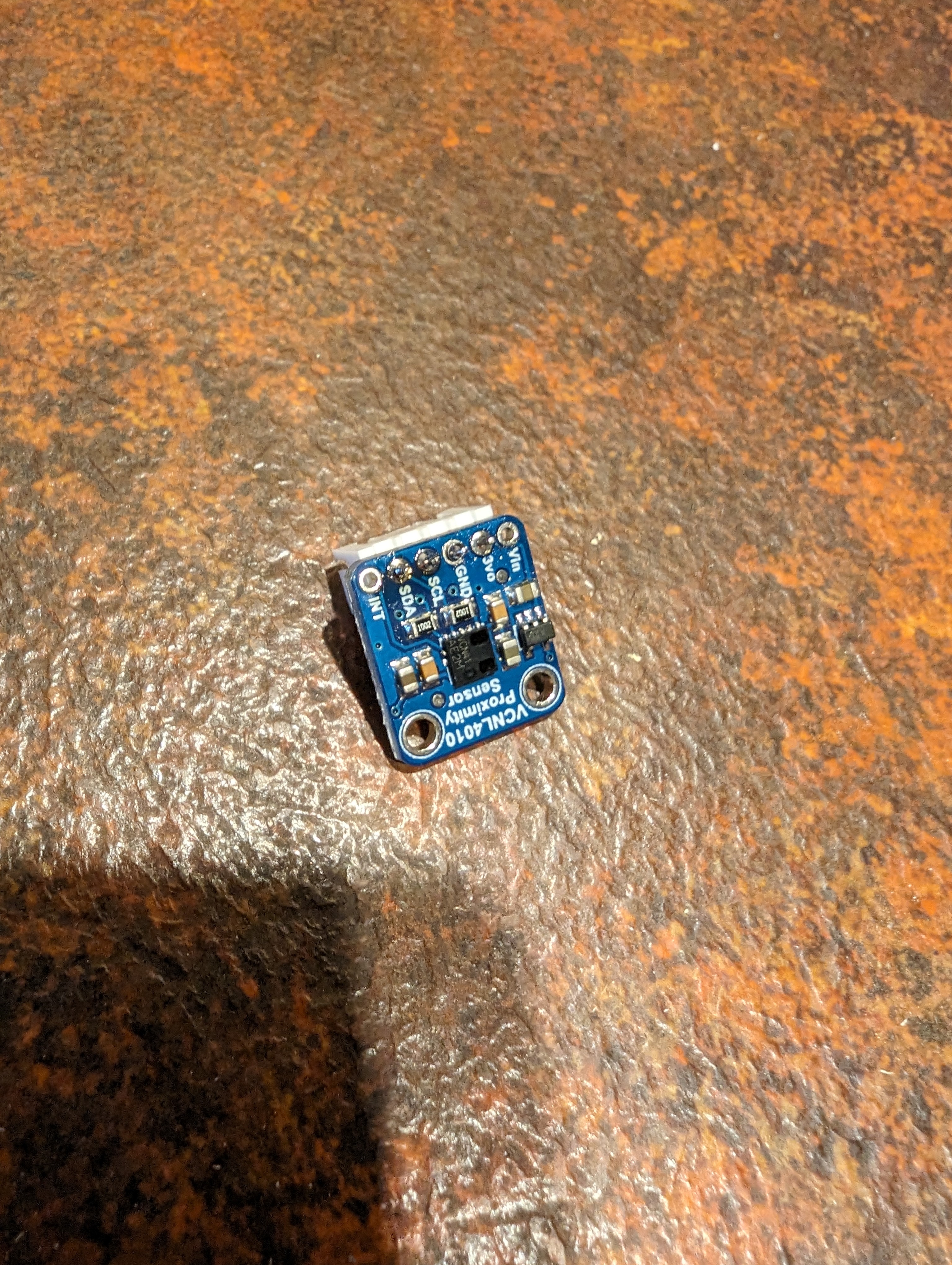
- 2x VCNL4010 proximity sensor
- ESP32 dev board with antenna
- Bigger antenna
- Prototype board
- 2.54mm pitch JST connectors
- 2.54mm pitch pin header sockets
- 18650 battery
- 18650 Type-C charging module
- Battery holder
- 2x 5V 1.5W solar panels
- MCP1700-3302E LDO regulator
- 100uF electrolytic capacitor
- 100nF ceramic capacitor
- Resistors... I think I ended up using a 1 MOhm and a 330 kOhm
- Weatherproof junction box
- Nylon screw spacers
- Cable glands
- 12mm waterproof button
- Various cables and wires
- Paint and polyurethane spray to weatherproof the wood
Tools:
- Soldering iron
- Router for cutting grooves in wood
- Drill and hole saw bits
- Various files and sandpaper
For a start, I followed this guide to get me started on the power delivery portion, but I ended up using much higher valued resistors since I found that I was losing more battery charge through the voltage divider than I was from the ESP32 or proximity sensors.
Once I'd tested the concept with the parts just laying in a jumble on the table, it was time to get to work.
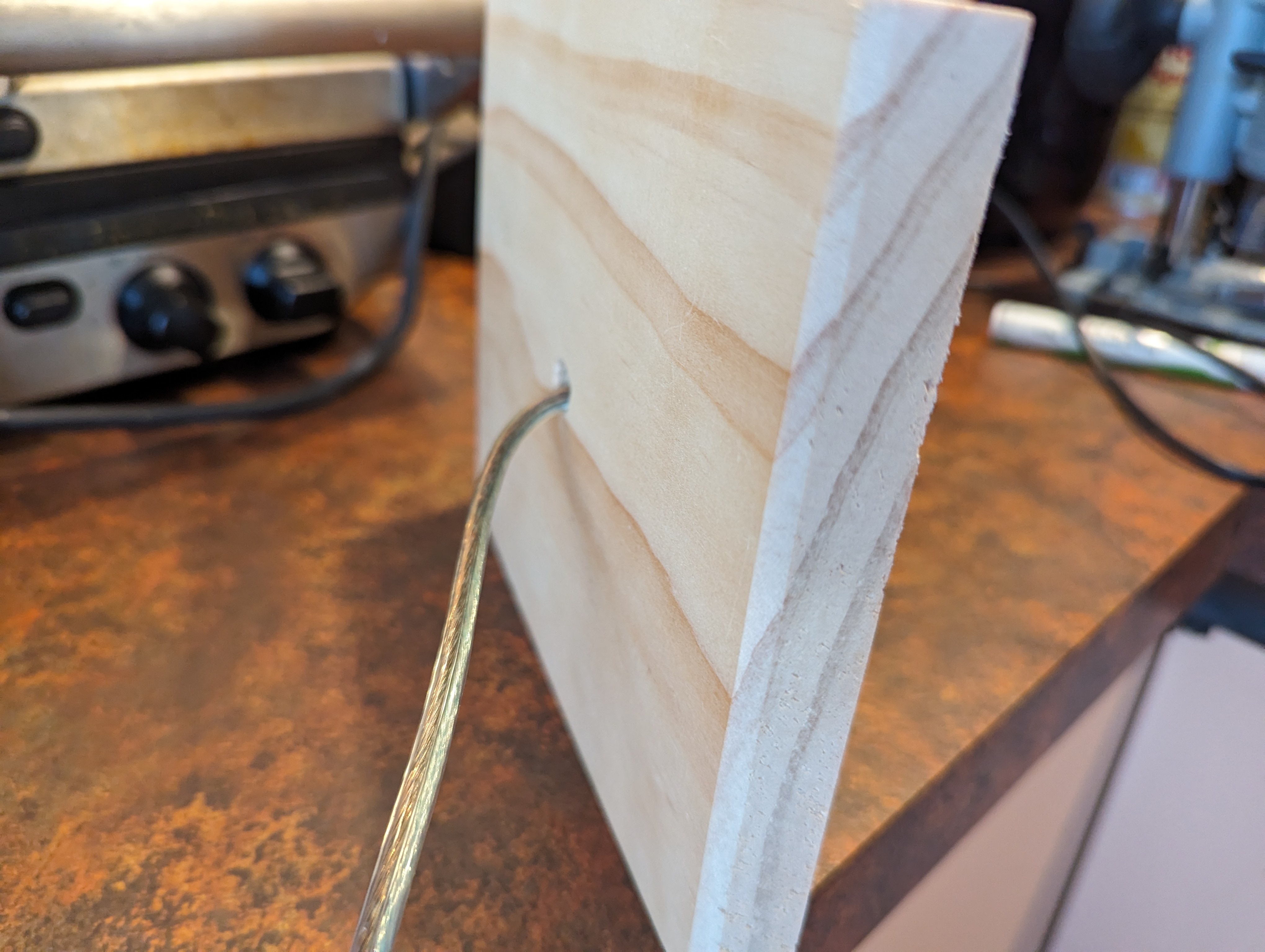
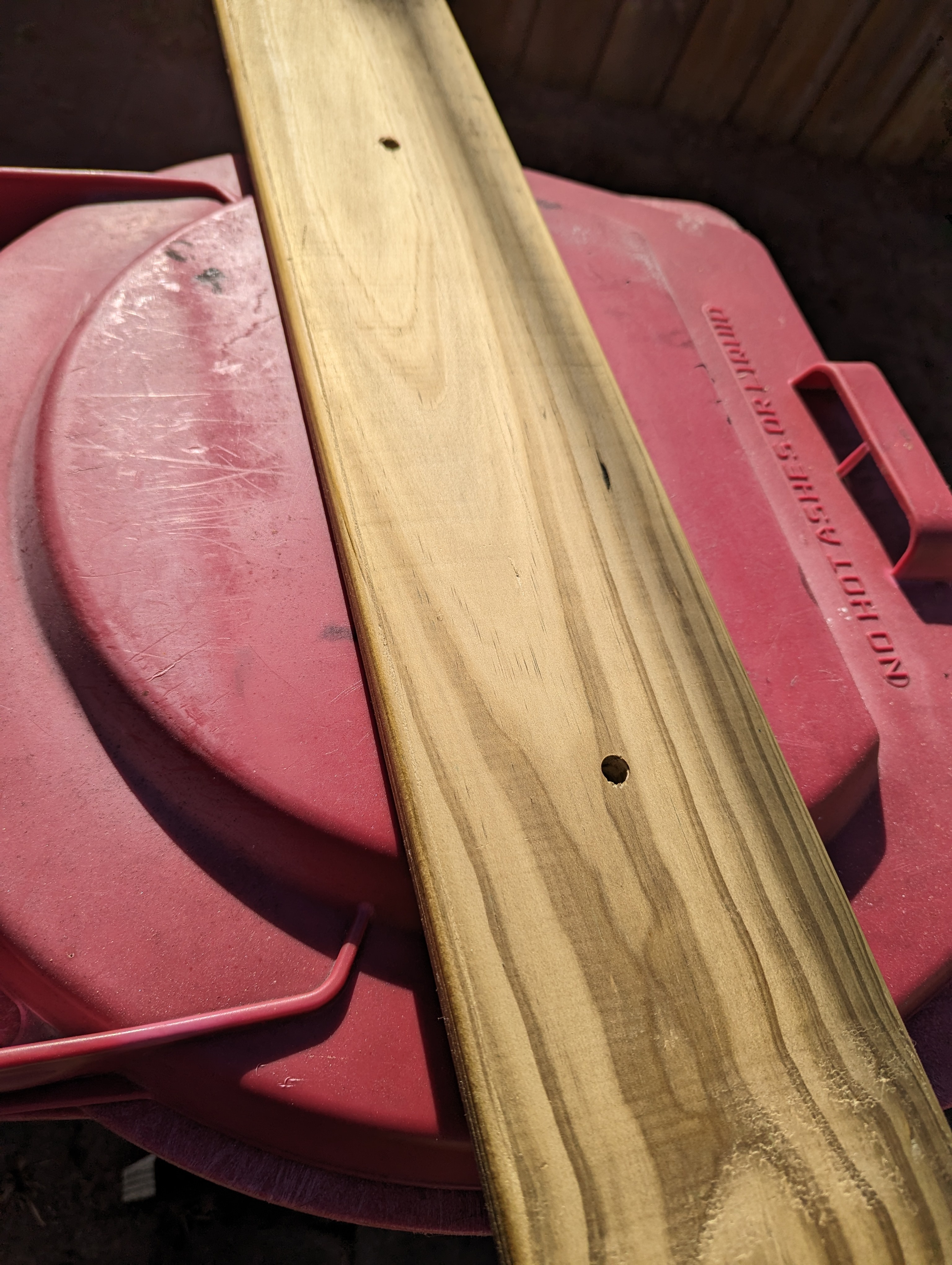
I started by cutting a plank of pine to fit my mailbox, chamfering the ends to make space for the metal joins. I routed out some spaces for the tops of the bolts that hold the mailbox down.
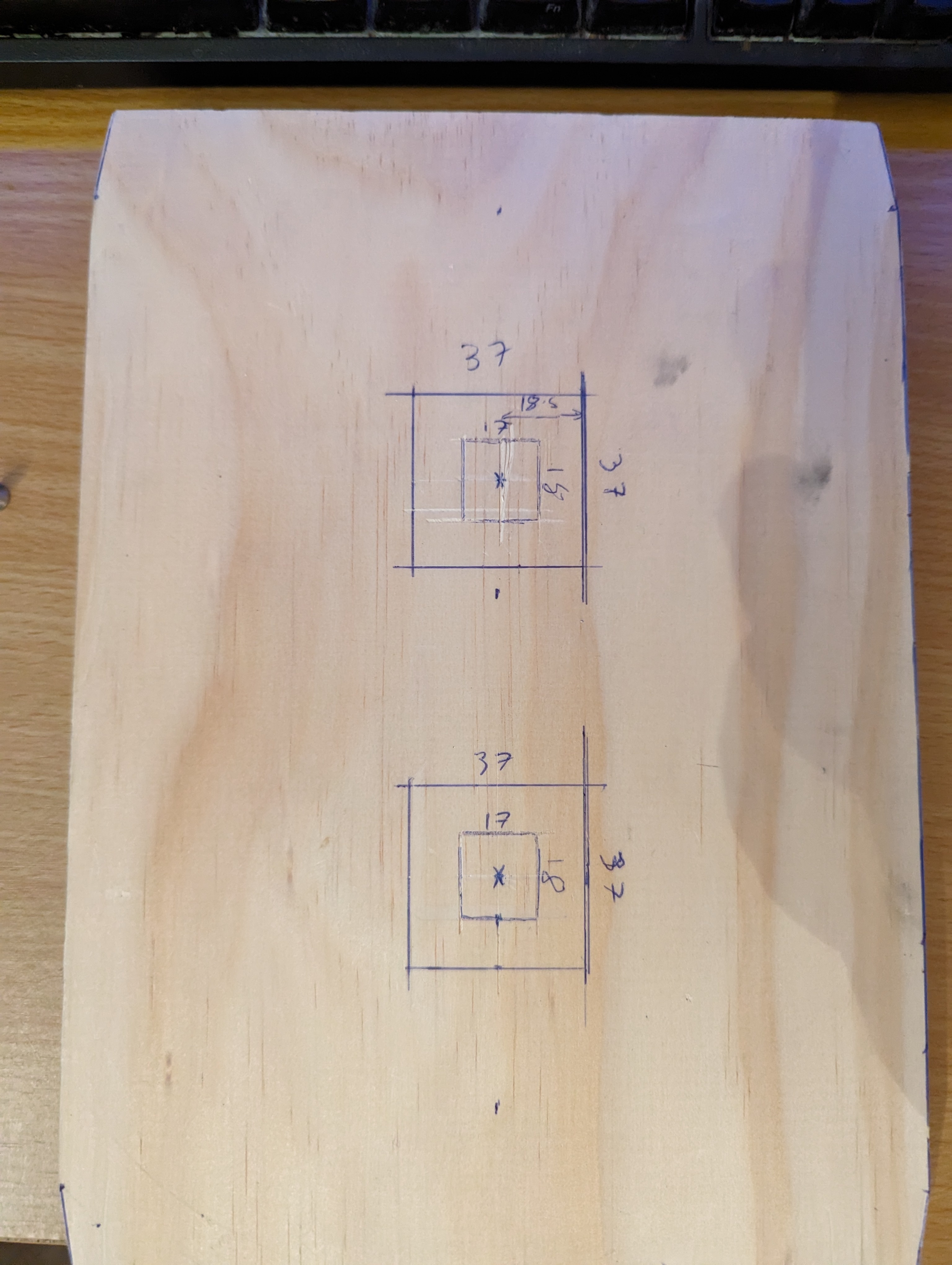
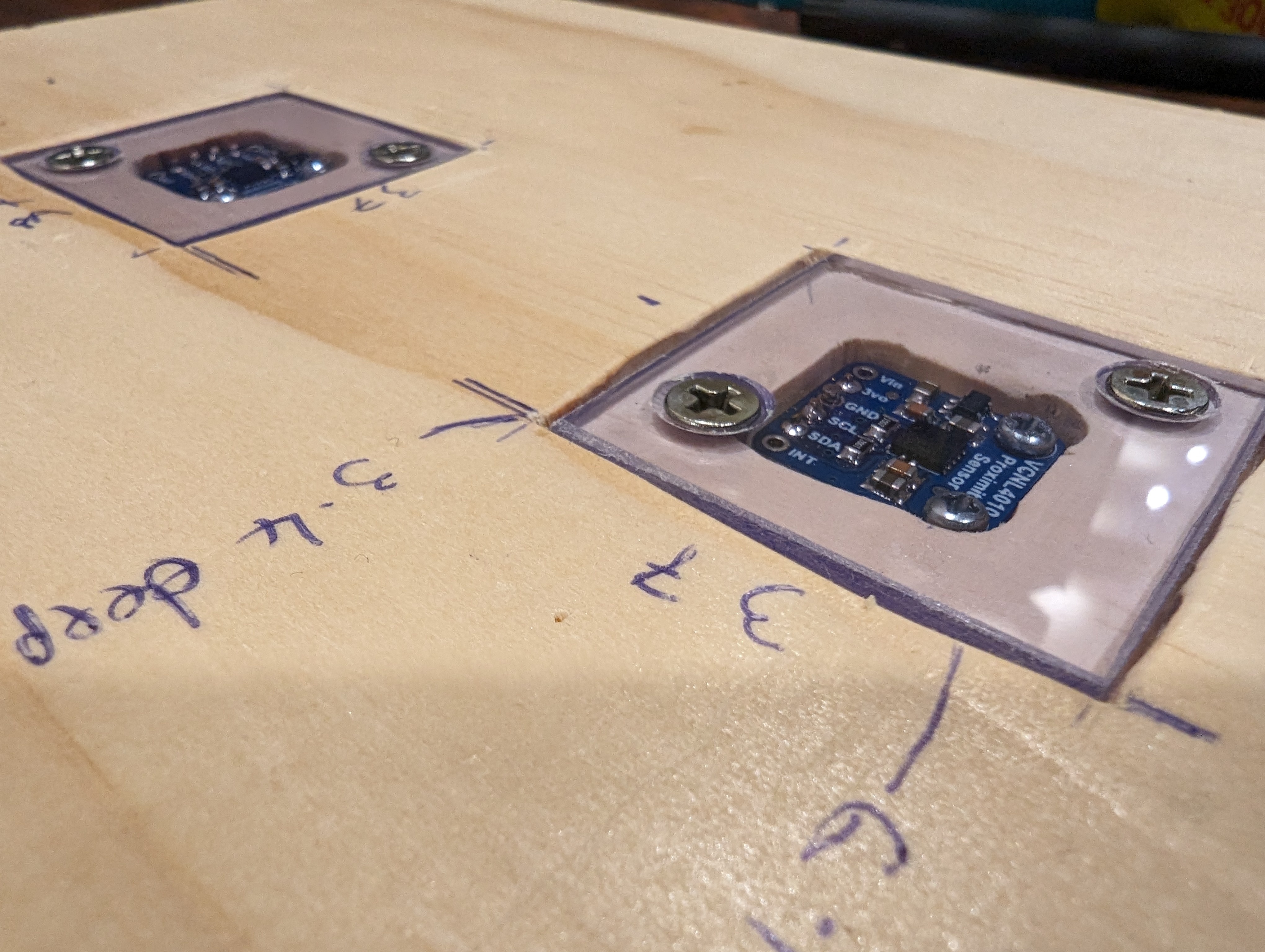
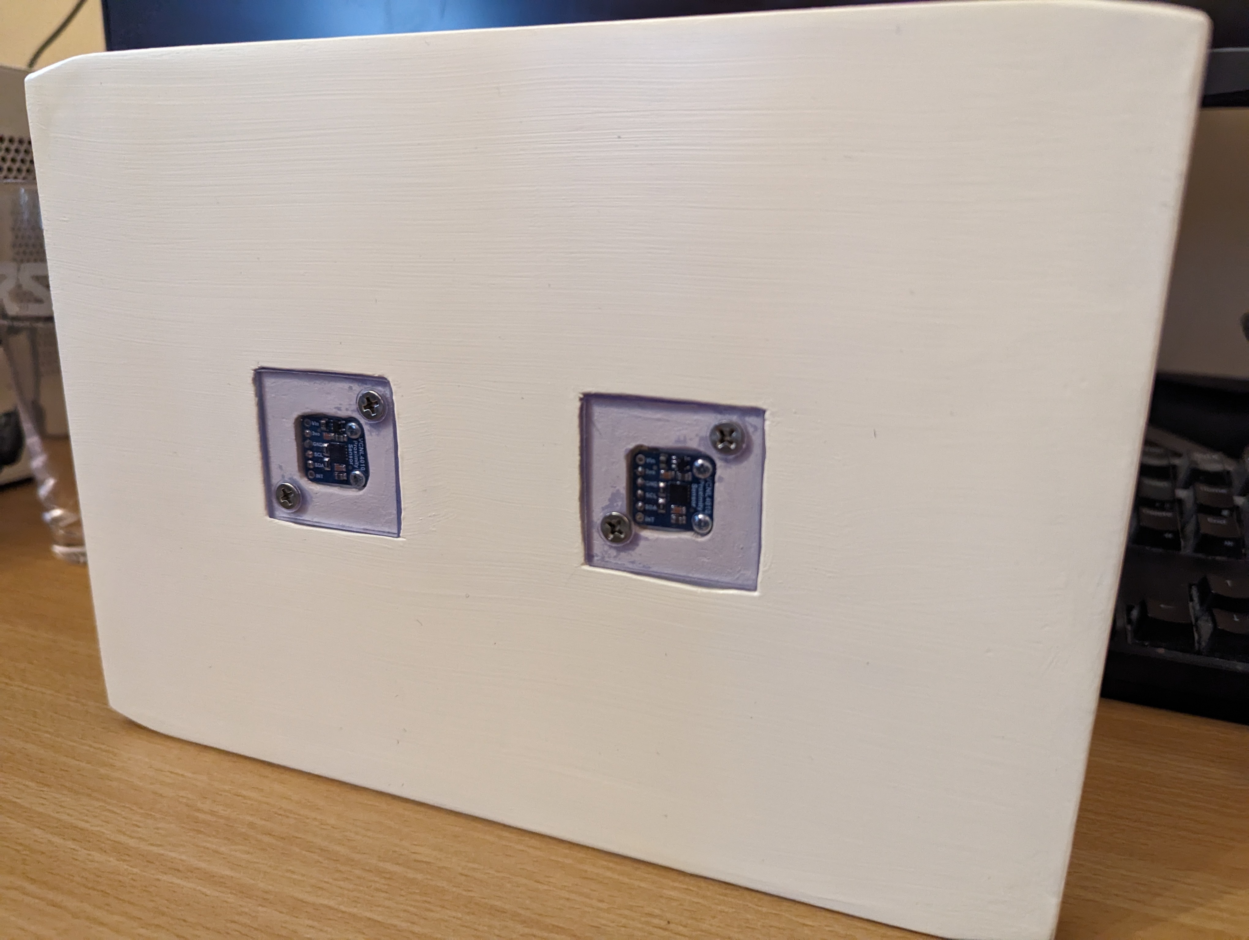
Measured out where the sensors should go, along with a surrounding space to screw down some little perspex windows to cover them. The idea I wanted was for the mail to be able to slide over the sensors without getting caught on them, as well as to protect them from dust.
Routed out the dents and cleaned them up with a chisel and sandpaper. Cut the perspex to shape for a test fit.
On the other side, I routed out a notch for the cable to access the sensors.
I had originally planned to just solder wires into the sensors, but then I realised JST connectors would fit perfectly into the sensors. This meant I had to widen the holes somewhat, which I did with a small chisel and file.
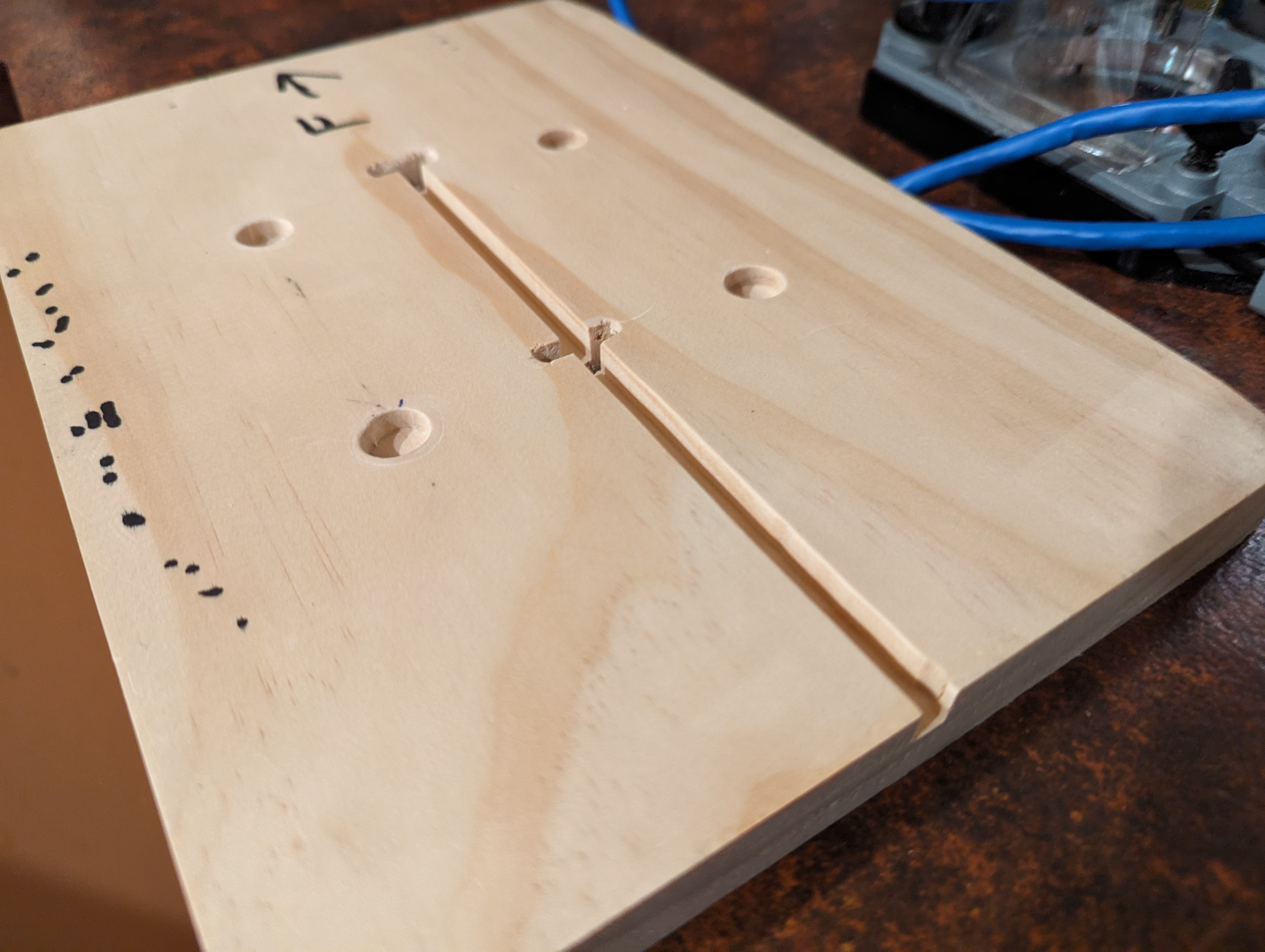
I got a bit lazy with making screw holes to hold down the perspex, so they're not in as neat a place as I'd like. If I did this again I'd measure properly for their placement. Still, with countersinking they hold down the perspex well and nothing sticks up for mail to get caught on.
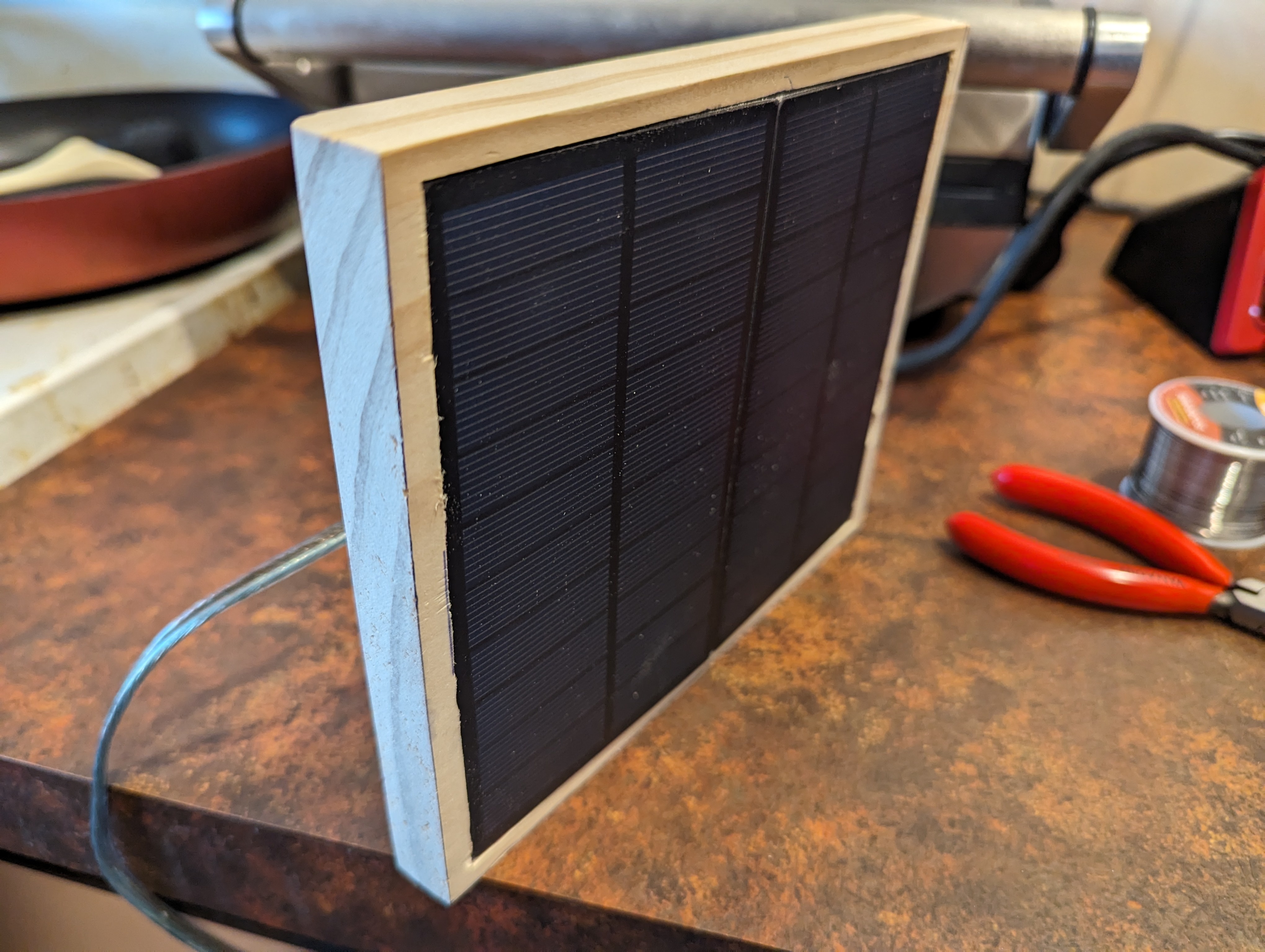
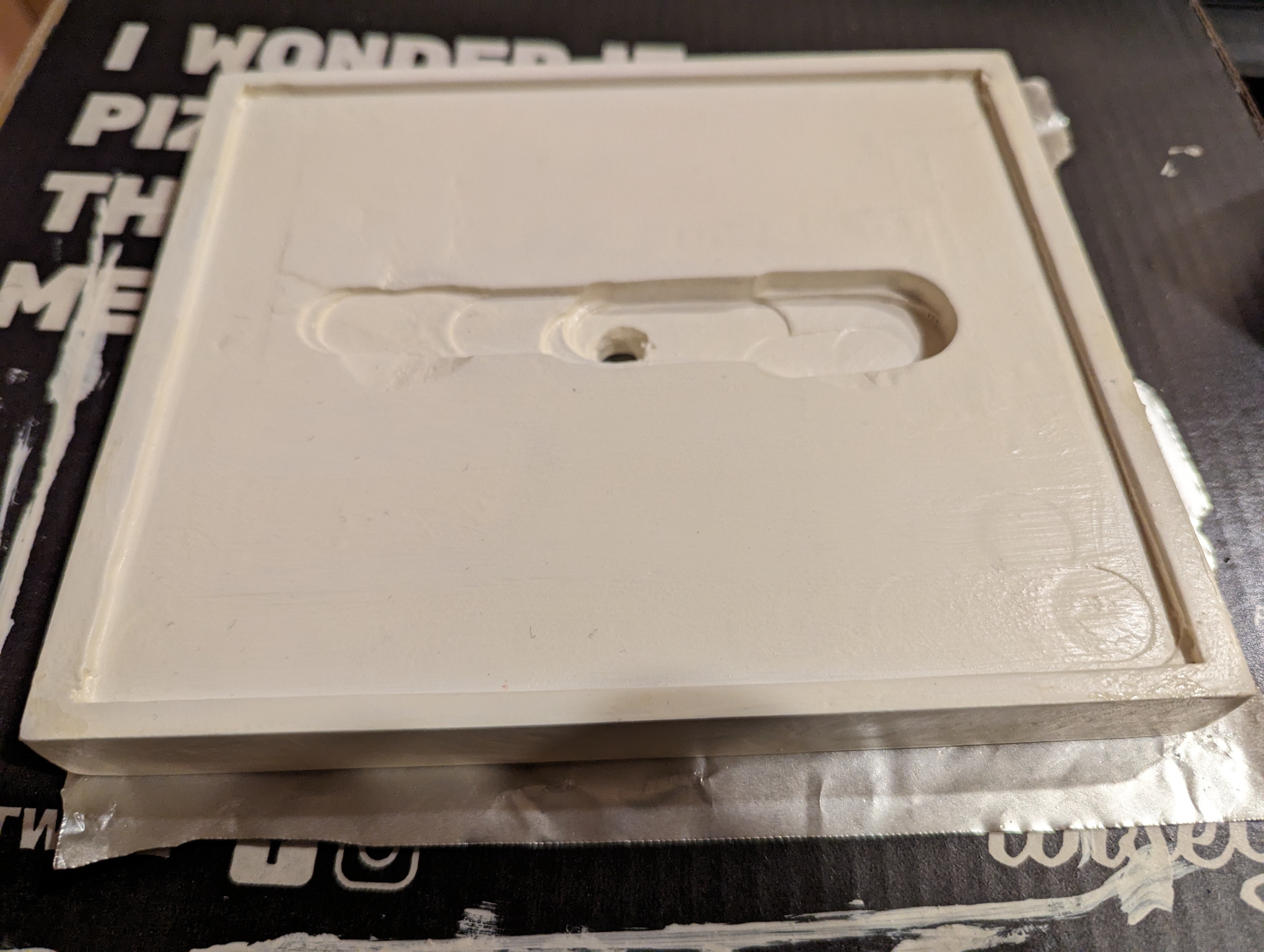
I also got started on making a housing for the solar panels. I used the router to carve out a 1-2mm area for them to sit in, and a much deeper ditch linking the two terminals, which you'll see in a later picture. For now, here's how they look sitting in it.
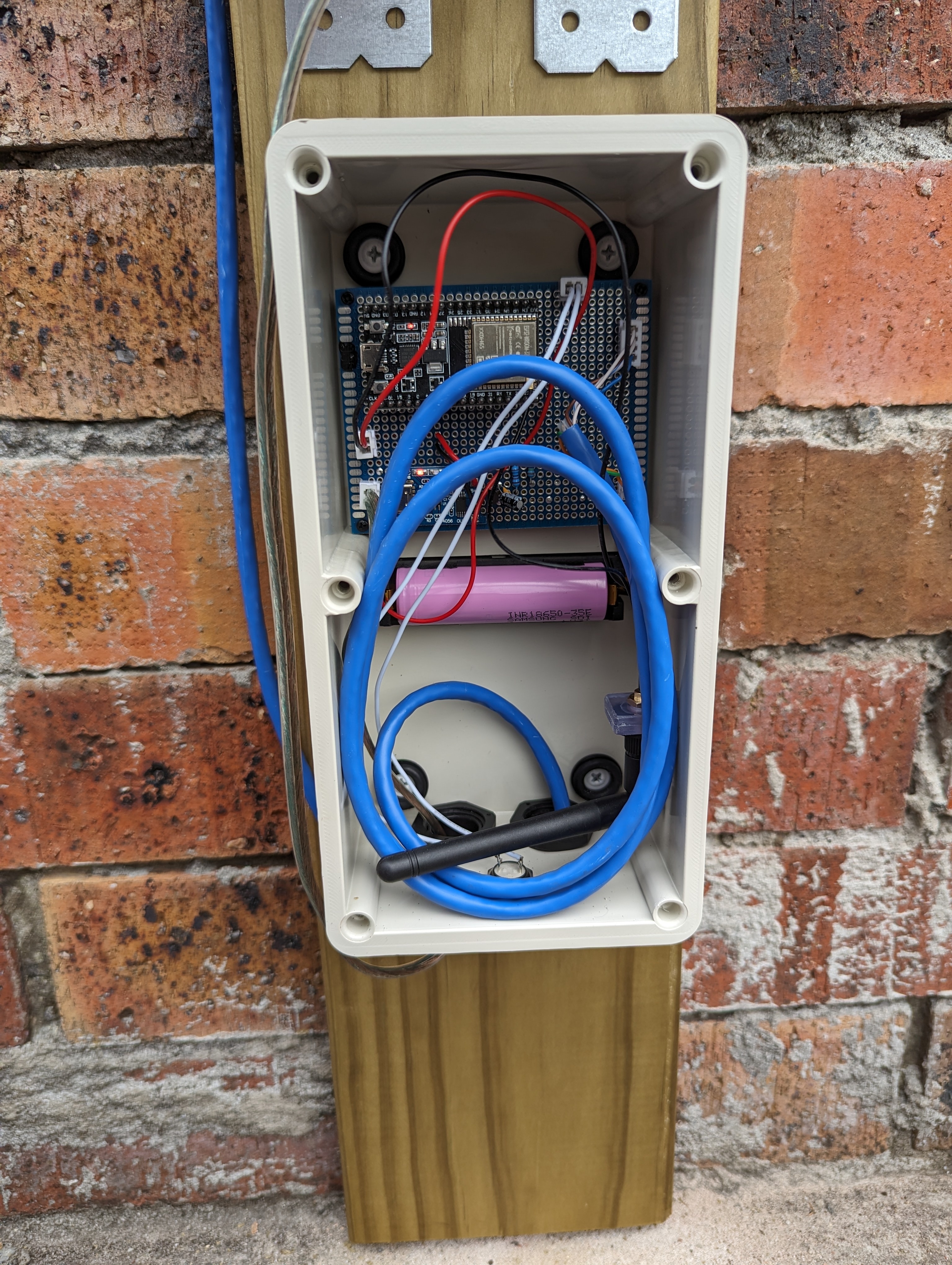
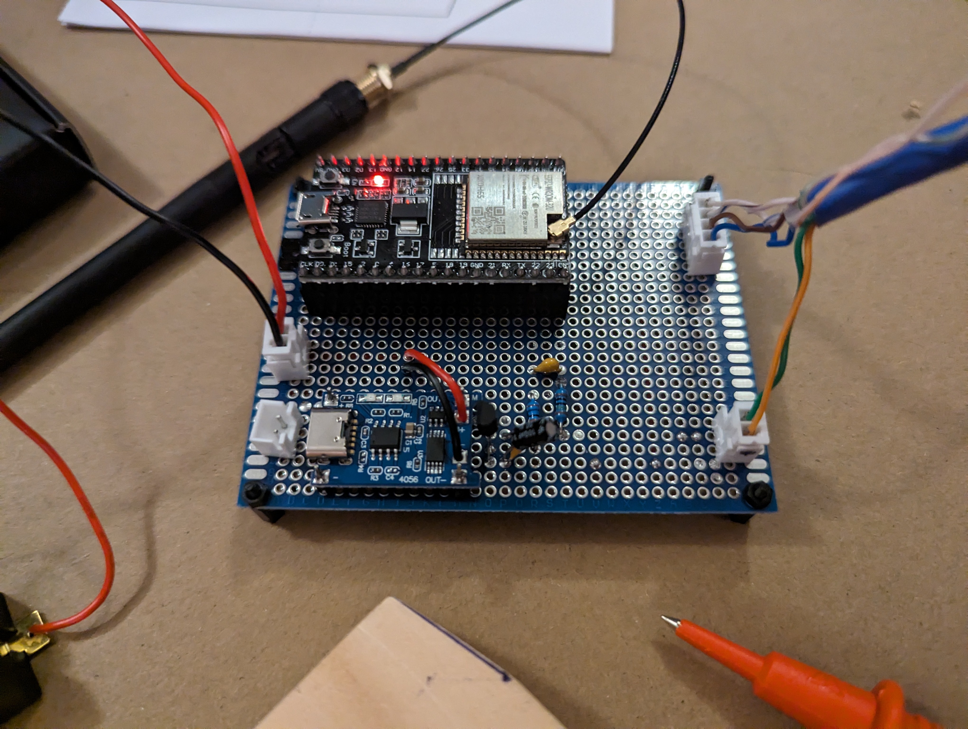
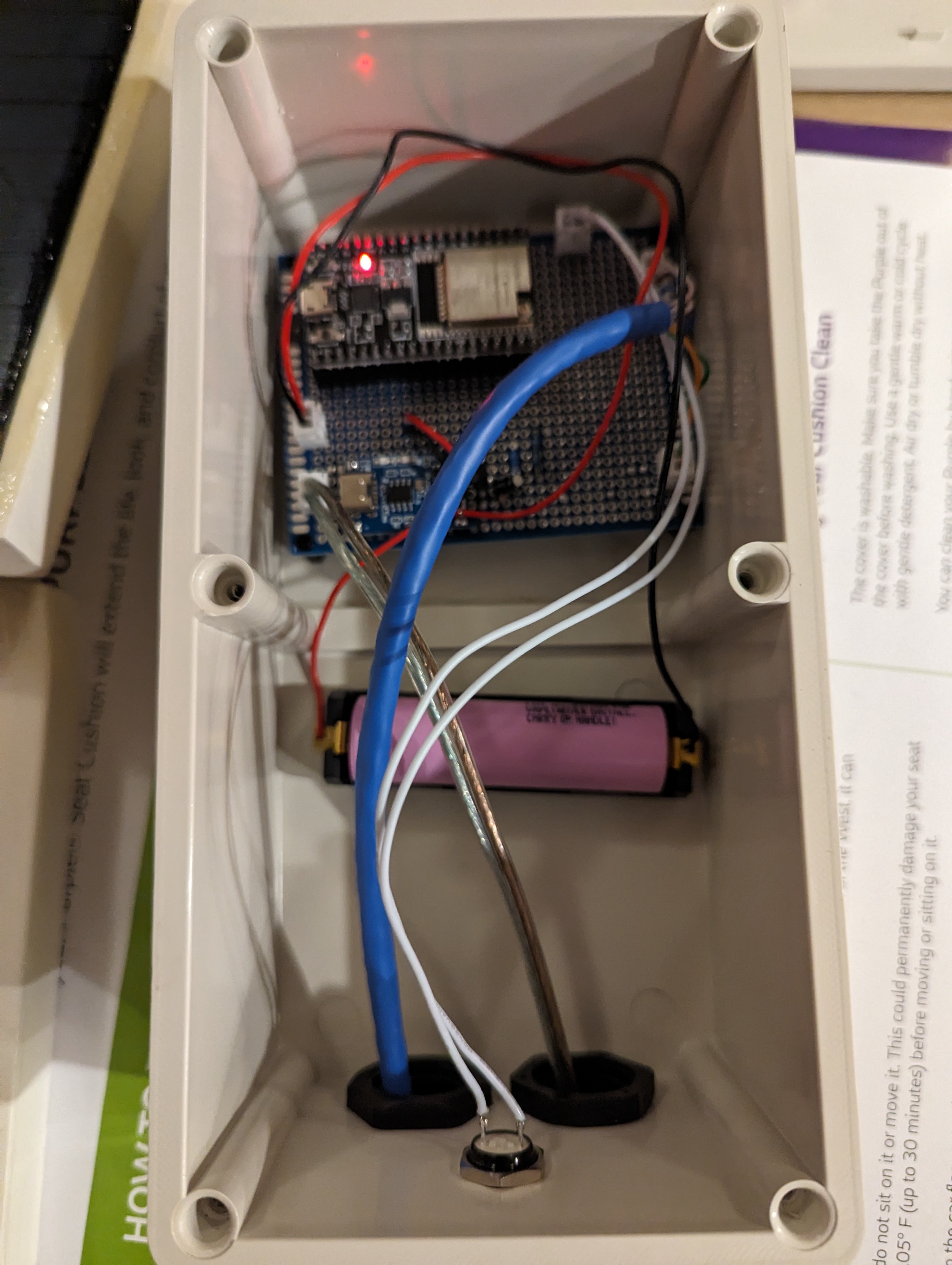
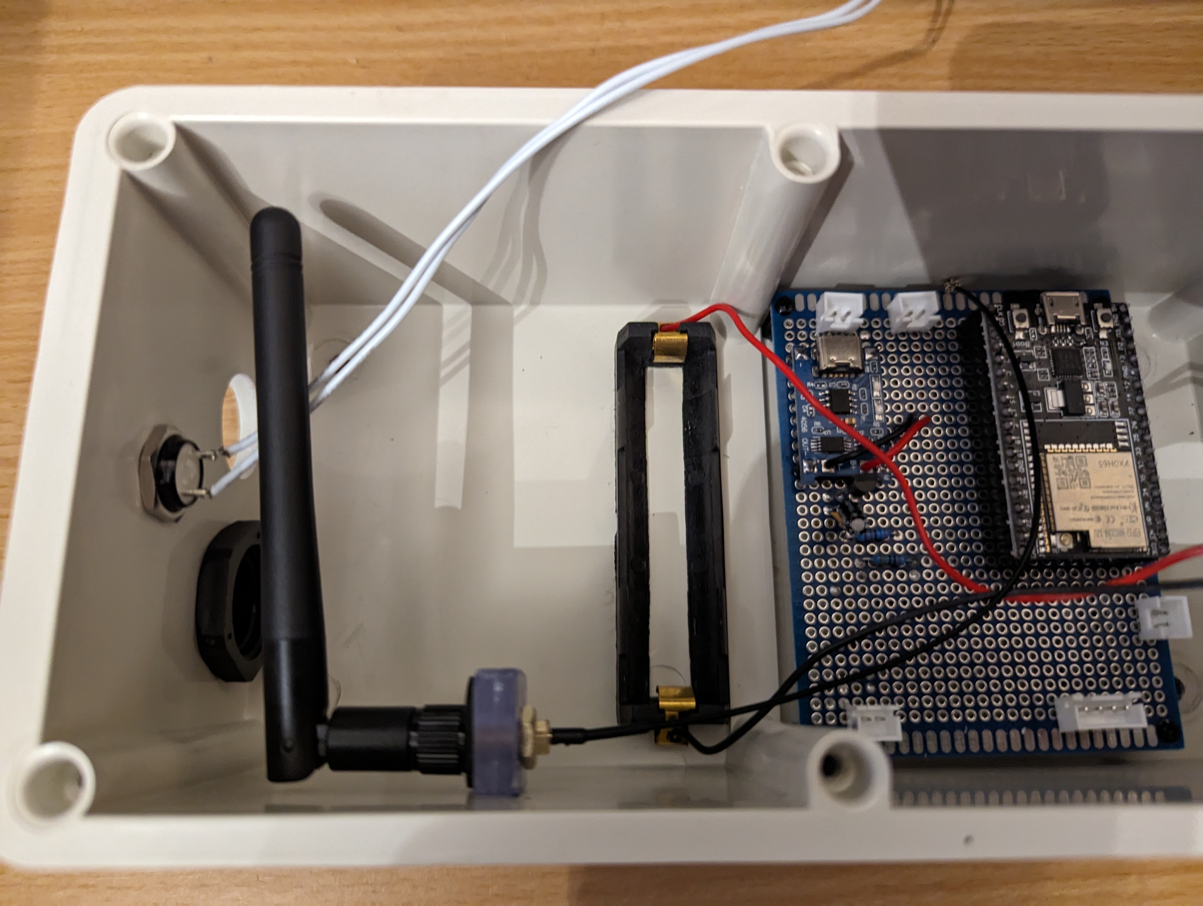
Wiring up the prototype board was next. Again, see the article I linked above for how this works. I used pin headers to allow the ESP32 dev board to be slotted in and out, just in case I ever needed to take it out for replacement or reprogramming. Also the JSTs on the prototype board are for connecting the battery (top left), connecting the solar panels (bottom left), providing power to the sensors (bottom right) and clock and data lines for the sensors (top right). Since the sensors are both using the same I2C bus address and cannot be configured otherwise, I had to run two clock and data lines, but if I'd found sensors that could have different addresses I could have just used one of each. I didn't take a photo of the board at this stage, but I later added another header to connect a button to reset the ESP32 from the outside.
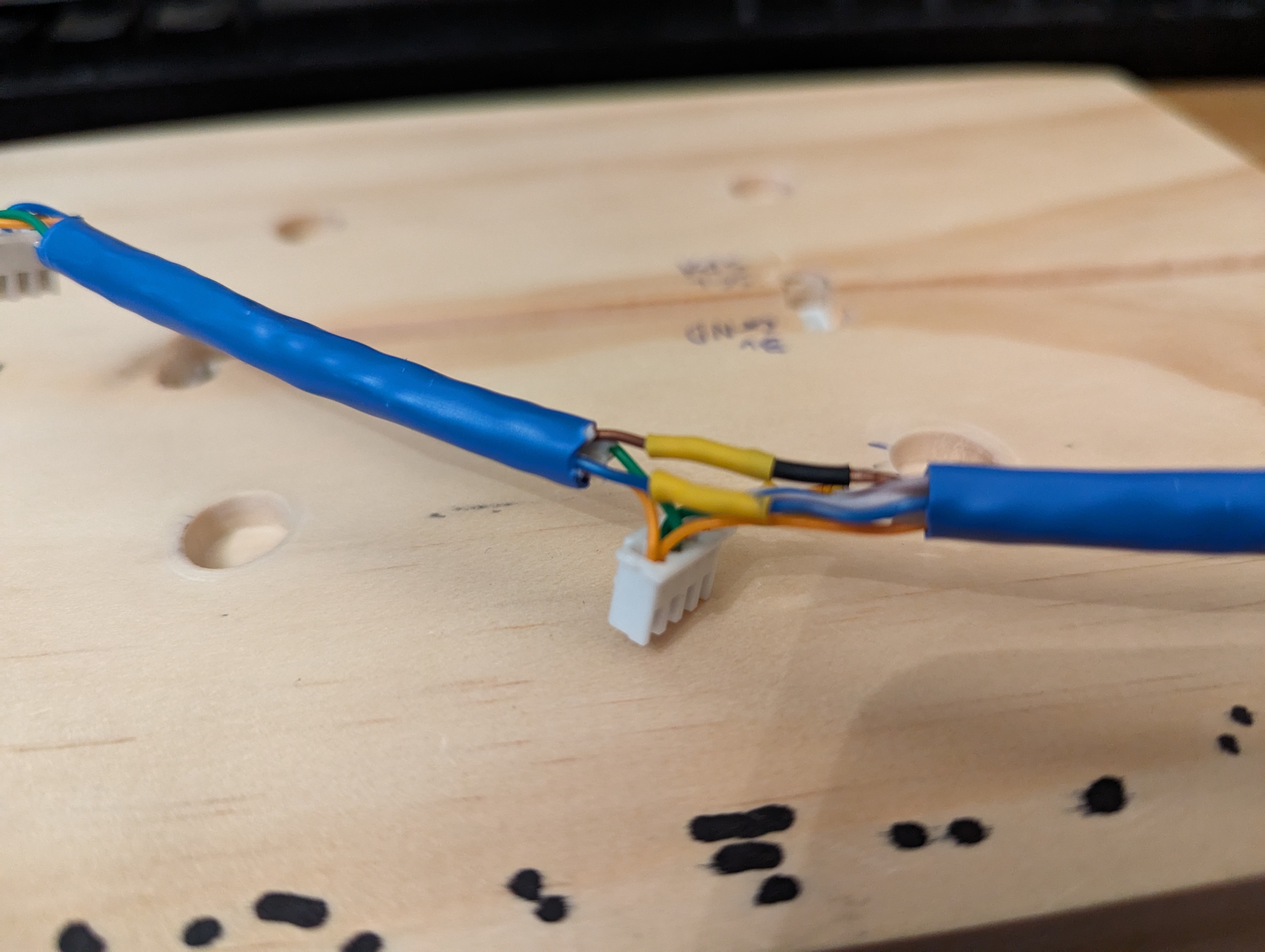
I also made the data and power cable for the sensor board.
The solar panel housing and 'sensor plate' were both painted and treated with polyurethane spray to protect them from rain and humidity.
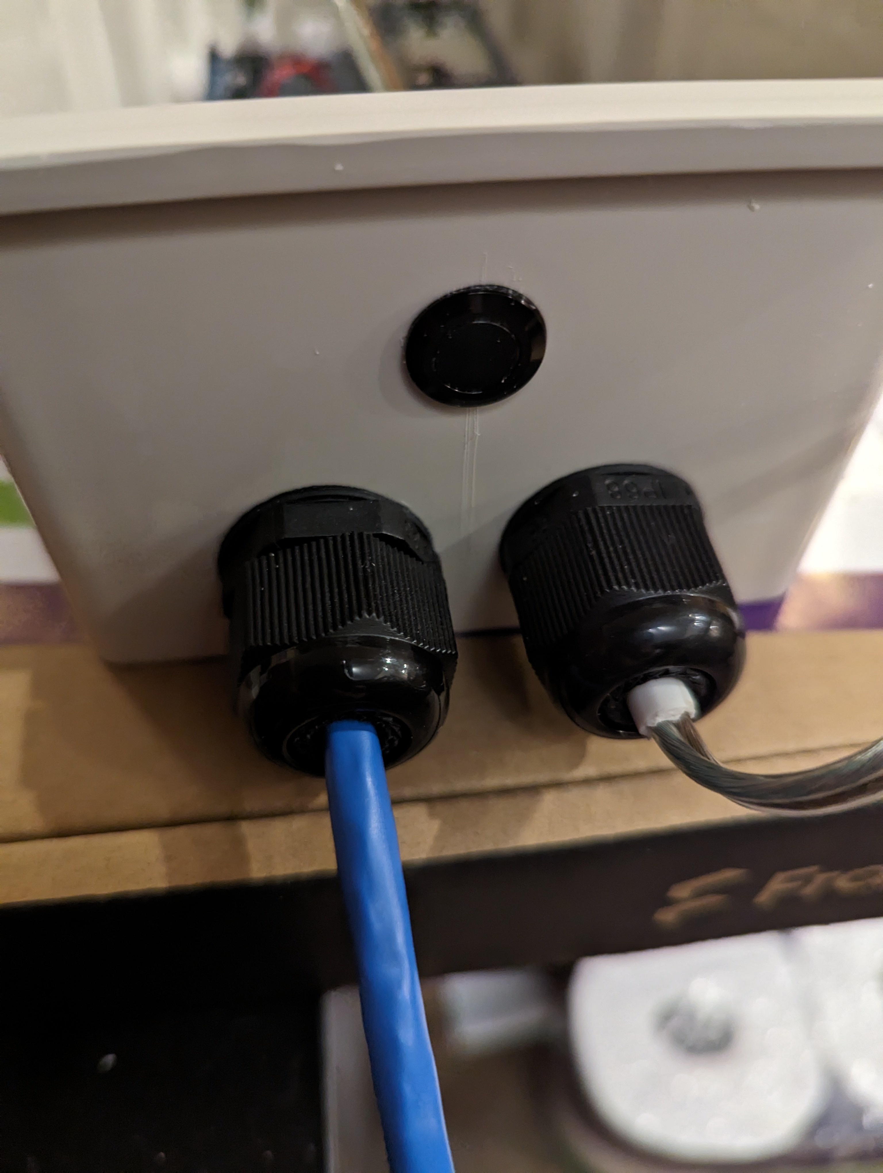
I drilled holes in the weatherproof box to fix the cable glands and the weatherproof button. In the case of the solar panel wire, I had opted to buy speaker wire since I figured it would be easier to run in the channel between the two solar panels, being flat. But that also made it not really fit the cable glands that great. I ended up stripping some of the outer sheath off some 2 wire power cable I had, and wrapping that around the part of the speaker wire that gets clamped in the glands, just to make a reasonable seal. These all were on the side I decided I would mount at the bottom, so water wouldn't be able to easily fall into the box.
Final test fit. I later used epoxy glue to glue down the nylon headers and the battery holder inside the box.
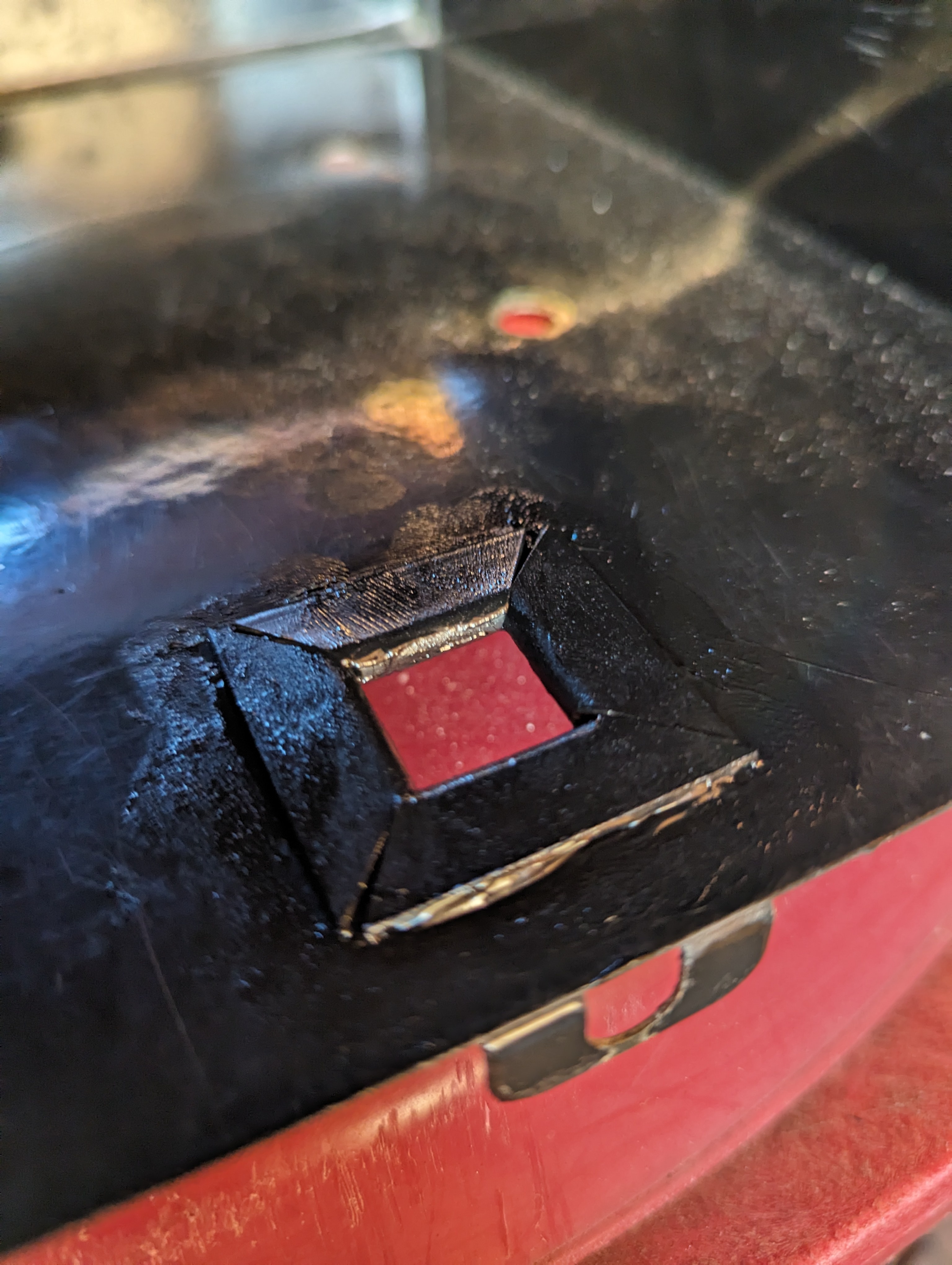
The mailbox itself also needed a hole in the bottom for the sensor cable to come out. After drilling a hole and filing it into a square shape, I cut some rubber grommet strip to size and fitted it around the hole, with some marine silicone adhesive to protect the sharp metal edges from water and to hold the grommet strip in place.
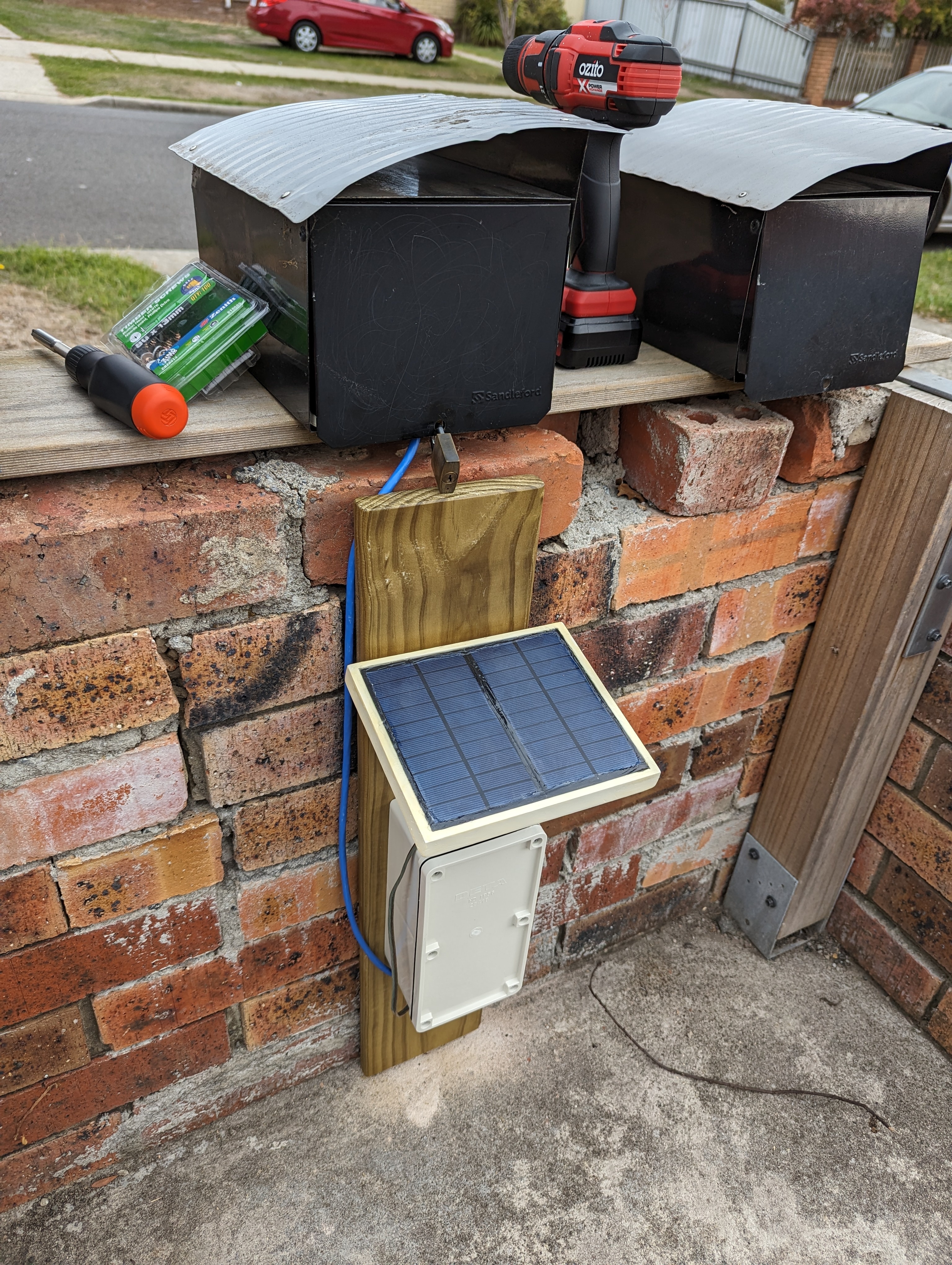
I'd drilled some holes in the brick wall my mailbox sits upon for masonry anchors, and this piece of treated pine got the last of my polyurethane spray, just in case.
Using a two pieces of the leftover perspex glued together, I made an internal mount for the antenna, figuring it would be best to not have the thing either floating around freely inside the box or sticking out the side where people could potentially break it off.

Finally, after weeks of off and on work, it was ready to install.
The ESPHome coding used my VCNL4010 component, and if anyone is interested I can share it but it's kinda a large file.
It was a long running project, but I finally did it. I built what I'm calling a smart mailbox that communicates locally with Home Assistant via ESPHome.
Parts:
- Pine plank roughly the width of my mailbox
- Treated pine plank for mounting
- Thin sheet of perspex or similar transparent plastic
- 2x VCNL4010 proximity sensor
- ESP32 dev board with antenna
- Bigger antenna
- Prototype board
- 2.54mm pitch JST connectors
- 2.54mm pitch pin header sockets
- 18650 battery
- 18650 Type-C charging module
- Battery holder
- 2x 5V 1.5W solar panels
- MCP1700-3302E LDO regulator
- 100uF electrolytic capacitor
- 100nF ceramic capacitor
- Resistors... I think I ended up using a 1 MOhm and a 330 kOhm
- Weatherproof junction box
- Nylon screw spacers
- Cable glands
- 12mm waterproof button
- Various cables and wires
- Paint and polyurethane spray to weatherproof the wood
Tools:
- Soldering iron
- Router for cutting grooves in wood
- Drill and hole saw bits
- Various files and sandpaper
For a start, I followed this guide to get me started on the power delivery portion, but I ended up using much higher valued resistors since I found that I was losing more battery charge through the voltage divider than I was from the ESP32 or proximity sensors.
Once I'd tested the concept with the parts just laying in a jumble on the table, it was time to get to work.
I started by cutting a plank of pine to fit my mailbox, chamfering the ends to make space for the metal joins. I routed out some spaces for the tops of the bolts that hold the mailbox down.
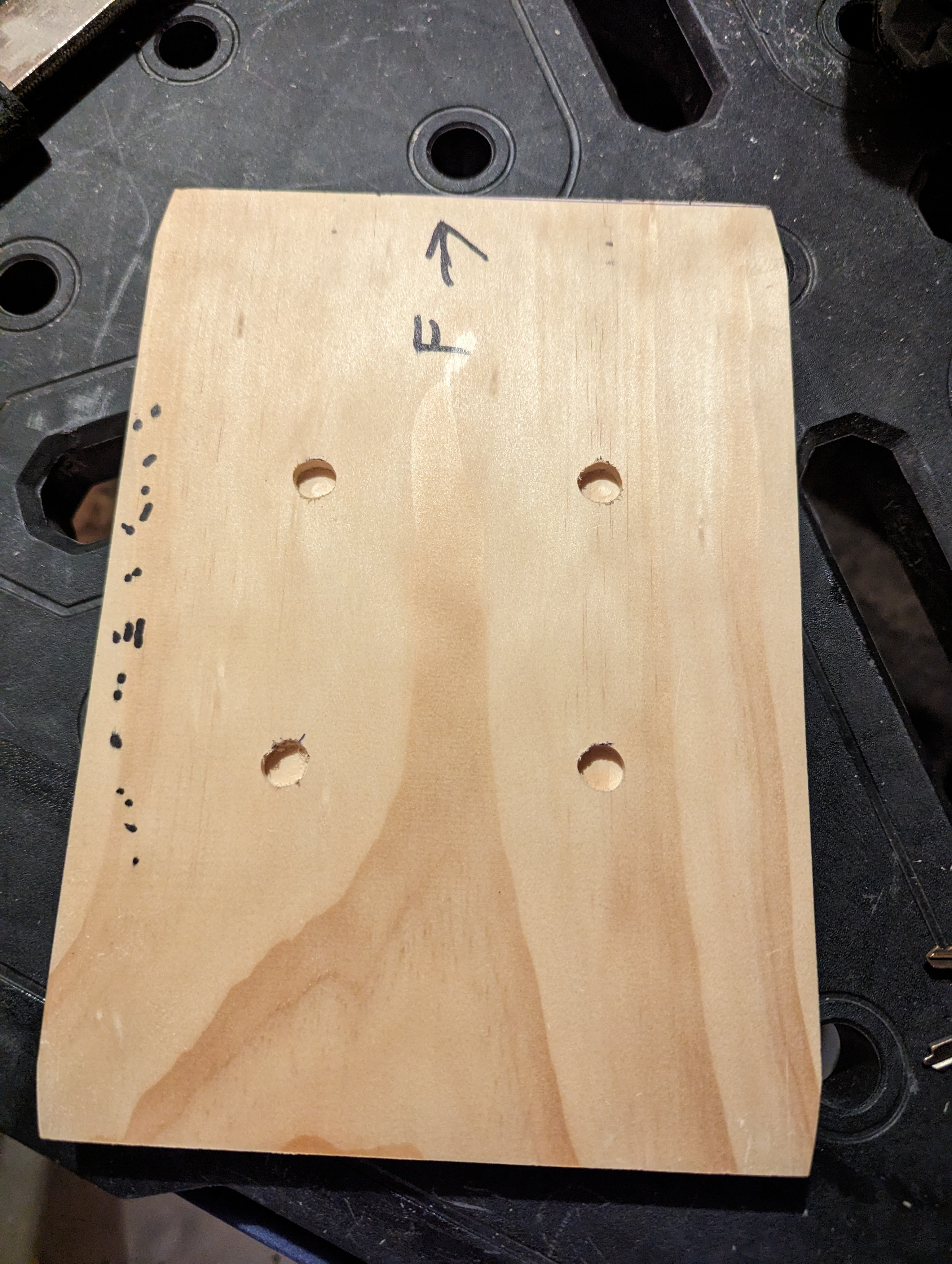
Measured out where the sensors should go, along with a surrounding space to screw down some little perspex windows to cover them. The idea I wanted was for the mail to be able to slide over the sensors without getting caught on them, as well as to protect them from dust.
Routed out the dents and cleaned them up with a chisel and sandpaper. Cut the perspex to shape for a test fit.
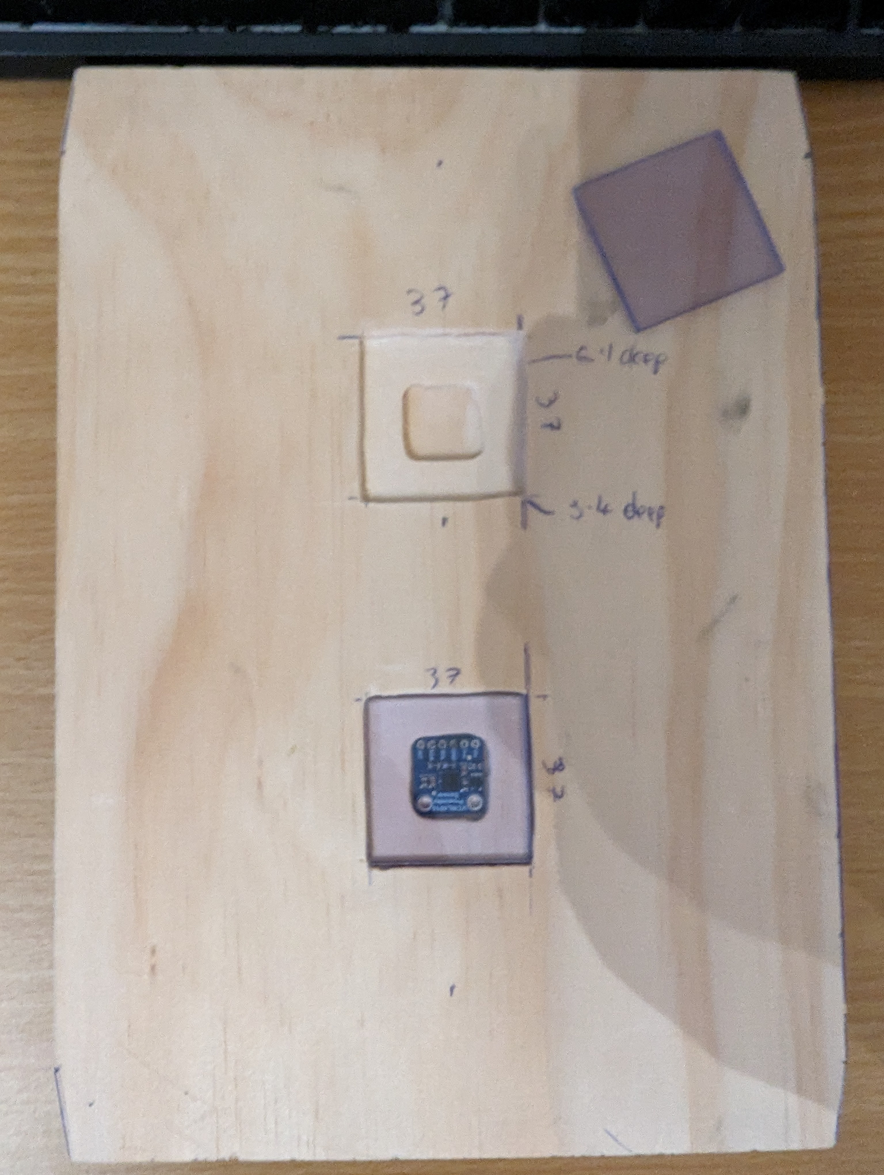
On the other side, I routed out a notch for the cable to access the sensors.
I had originally planned to just solder wires into the sensors, but then I realised JST connectors would fit perfectly into the sensors. This meant I had to widen the holes somewhat, which I did with a small chisel and file.
I got a bit lazy with making screw holes to hold down the perspex, so they're not in as neat a place as I'd like. If I did this again I'd measure properly for their placement. Still, with countersinking they hold down the perspex well and nothing sticks up for mail to get caught on.
I also got started on making a housing for the solar panels. I used the router to carve out a 1-2mm area for them to sit in, and a much deeper ditch linking the two terminals, which you'll see in a later picture. For now, here's how they look sitting in it.
Wiring up the prototype board was next. Again, see the article I linked above for how this works. I used pin headers to allow the ESP32 dev board to be slotted in and out, just in case I ever needed to take it out for replacement or reprogramming. Also the JSTs on the prototype board are for connecting the battery (top left), connecting the solar panels (bottom left), providing power to the sensors (bottom right) and clock and data lines for the sensors (top right). Since the sensors are both using the same I2C bus address and cannot be configured otherwise, I had to run two clock and data lines, but if I'd found sensors that could have different addresses I could have just used one of each. I didn't take a photo of the board at this stage, but I later added another header to connect a button to reset the ESP32 from the outside.
I also made the data and power cable for the sensor board.
The solar panel housing and 'sensor plate' were both painted and treated with polyurethane spray to protect them from rain and humidity.
I drilled holes in the weatherproof box to fix the cable glands and the weatherproof button. In the case of the solar panel wire, I had opted to buy speaker wire since I figured it would be easier to run in the channel between the two solar panels, being flat. But that also made it not really fit the cable glands that great. I ended up stripping some of the outer sheath off some 2 wire power cable I had, and wrapping that around the part of the speaker wire that gets clamped in the glands, just to make a reasonable seal. These all were on the side I decided I would mount at the bottom, so water wouldn't be able to easily fall into the box.
Final test fit. I later used epoxy glue to glue down the nylon headers and the battery holder inside the box.
The mailbox itself also needed a hole in the bottom for the sensor cable to come out. After drilling a hole and filing it into a square shape, I cut some rubber grommet strip to size and fitted it around the hole, with some marine silicone adhesive to protect the sharp metal edges from water and to hold the grommet strip in place.
I'd drilled some holes in the brick wall my mailbox sits upon for masonry anchors, and this piece of treated pine got the last of my polyurethane spray, just in case.
Using a two pieces of the leftover perspex glued together, I made an internal mount for the antenna, figuring it would be best to not have the thing either floating around freely inside the box or sticking out the side where people could potentially break it off.
Finally, after weeks of off and on work, it was ready to install.
The ESPHome coding used my VCNL4010 component, and if anyone is interested I can share it but it's kinda a large file.
view more: next ›
Hard to say without having used Arch. I just really like Portage. It does some really neat things.