Also huh... I was quite happy with my Ender5 and have gradually replaced almost everything except the frame. I learned a lot from upgrading and tinkering with it.
Rolive
joined 3 years ago
I'm building my own. I have the Ender 5 of Theseus.
Induction is amazing. It works faster than gas and is easier to control.
Also it strongly affects the performance of the suction hood above. The gas combustion produces a huge extra volume which blows away particles and oil vapors away from the suction hood.
It significantly improves the air quality inside the kitchen.
I can print a really shitty one.
It's called the Machine Spirit.
Praise the Omnissiah!
It seemed to work.
Here they fill meat with regular water. As long as it's on the label it's allowed. It's still a scam.
I have prepaid Mullvad so will use that until it expires. Then they never get my money again.
Reddit is such a disgusting shit heap these days. There are still some subreddits worth lurking in but the majority is flooded with AI posts.
It used to be so nice.
How many Dragonball characters does it take to change a lightbulb?
One but it takes 30 episodes.
How many Mexicans does it take to change a lightbulb?
Just Juan.
Vd UP CHICKEEEEEEN!
I made an enclosure for build-in induction cooking hobs. The build-in models are usually much cheaper and have better features than the free-standing ones. The corner blocks and ventilation grills are 3D printed and the side panels are 6mm thick aluminium composite plates. The plates are glued to the corner blocks using epoxy.
The price of the ACP plates and glue combined is still far cheaper than the difference between build-in and free-standing induction hobs and it's quite a simple model.
Here is the model and design file.
https://www.printables.com/model/1769315-induction-hob-enclosure

Normally you'd post a FixMyPrint issue where the OP asks for a solution. Here instead I post an issue and the cause/solution immediately as well, hoping that it helps others.
This issue looks this way in a CoreXY printer, on a Cartesian printer you probably have only one axis looking weird.
The top part of the image has two printed objects in it, they're corner blocks for an enclosure I'm making. The right one has a bend in it. The toolhead would consistently move 1mm to the right or left at the exact same location. Normally a layer shift occurs due to warping or loose belts or hitting the infill somehow.
The left block is what it's supposed to look like.
Upon closer inspection of my belts it appears that one of them was stretched a small amount. These are cheap generic belts from Aliexpress that did last quite a while but were probably not the highest quality. At some point the filling material breaks and the belt stretches by a small amount. When that part of the belt goes over the stepper motor you get a layer shift.
Now I got Gates belts and hope that they last longer.

I'm designing a new toolhead for my heavily modified Ender 5. At the moment it uses a MicroSwiss all metal hotend with dual blower fans, a tiny 404010 fan on the heatbreak (barely enough) and on top of it an Orbiter 1.5 extruder.
It has been working quite well but I want to get something with higher flow capabilities to push print speeds. Perhaps even dual Orbiter extruders and two hotends.
After I'm done modifying the Ender5 it will have a 314x314 bed which should allow for dual hotends without losing too much space.
Ideally I end up with a new toolhead so that the old one may be kept as backup.
I have been eyeing the Orbiter V2 with the Phaetus Rapido UHF but I'm open to suggestions. What have you been using and do you have any advice? There are a ton of options.

I want to grow my own supply.

This is a customized version of the Ender 5 Mercury One.1 mod. I had two 10mm rods lying around that would fit the X axis and wanted to use the MGN12 rail for a custom CNC project instead. Please check the Printables link for more information as well as a FreeCAD file.
https://www.printables.com/model/1399143-ender-5-mercury-one1-x-10mm-rod-mod
I also think that having the hotend centered between two rails may allow for a larger reachable print area at some point. Later I want to remake the way the heated bed is mounted so that a larger bed can be used while still having the same Ender 5 footprint.
I don't think this should still be called an Ender 5 and this point. Perhaps a Frankender will do.
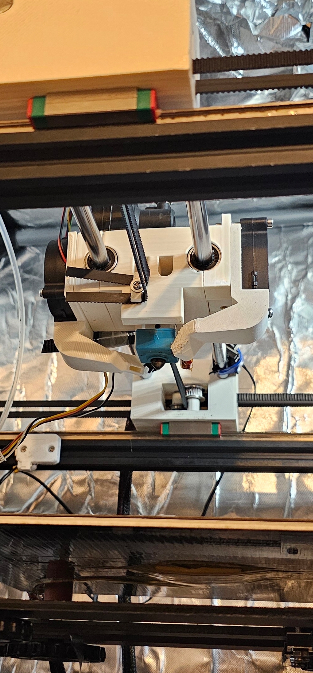
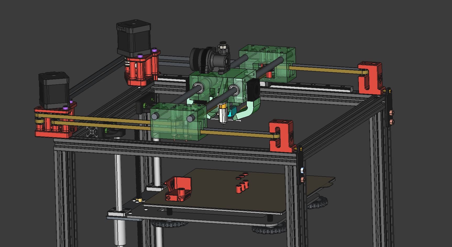
This is a WIP and at this point don't know if it's going to be successful or not. I'm currently building it. The idea is to use the Mercury One build but modify it so that it uses 10mm rods on the X axis instead of an aluminium extrusion with an MGN12 rail. I have a set of these rods on hand and want to use the MGN12 rail on a DIY CNC instead. These rods seem good enough for a 3D printer and I don't want to waste them.
I have decided to modify the Mercury One so that it has a different X assembly and a completely custom toolhead that houses the stock Ender5 hotend or a MicroSwiss hotend coupled with an Orbiter 1.5 extruder. Later I'll make a different toolhead for a better hotend but for now the MicroSwiss is good enough.
The red parts are original MercuryOne parts, the green ones are the ones I designed. I haven't bothered with rounding or chamfering yet. I have also imported some things from GrabCAD such as the BLtouch, hotend and fans.
This is quite the Frankenstein creation and I wonder, what am I supposed to call it? It barely resembles an Ender5 at this point, only the frame does.
I feel a bit bad for still using Gdrive but here's the FreeCAD file. I only put things in Gdrive that I want to share publicly so idc if they spy on me. https://drive.google.com/file/d/1WFskq_OpdML4qeyOsKfkcaarW1QUJOB5/view?usp=sharing
view more: next ›
Pardon my French, the server is down.