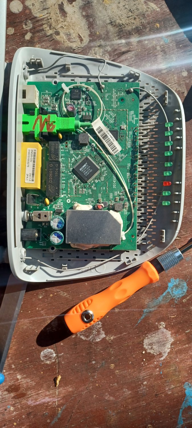
Ask Electronics

3732 readers
94 users here now

For questions about component-level electronic circuits, tools and equipment.

Rules

1: Be nice.

2: Be on-topic (eg: Electronic, not electrical).

3: No commercial stuff, buying, selling or valuations.

4: Be safe.


founded 2 years ago
MODERATORS
151


The lower part of my screen is updated one frame earlier than the upper part. I was able to isolate the error to the HDMI output of my laptop. The screen or cable is not broken, as I don't get these errors with other connected devices. I am assuming it is some hardware defect. Does anyone know what it could be and how I could fix it? Here are a few pictures that show the problem: pixelfed

Solved: Ok, it seems to have been a software problem. That had to do with the sync. I have installed ubuntu on the laptop for now and everything works again. Some update seems to have shot something. I am now using a LTS version.

152
4
submitted 2 years ago* (last edited 2 years ago) by Froghut@lemmy.dbzer0.com to c/askelectronics@discuss.tchncs.de


I'm trying to build a esp8266 weather station and got some MCP1700-3302E to power the esp8266 from a lipo. But when I connect the lipo to the MCP1700 (looking at it flat spot at the front, ground left, Vin in the middle and Vout on the right) I get no output at Vout. I googled and could not find anything. I tested 5 different ones and it's the same for all of them. Could I just have a batch of broken ones? Edit: attached a picture of my very simple test setup Edit 2: I just connected three lipo directly to Vin, that seems to work without any problems (at least for a few days now)

153


Questions:

  • Can you test 450V high ripple current caps with a any old desktop RCL meter?
  • Has digikey shipped me faulty units?

Background:

I've gotten a couple of 660uF (not a typo, it's some weird high ripple current caps for an outdoor AC unit) 450V caps to replace some that I decided were duds. Normally I only measure components when troubleshooting, but this being 20USD with vat devices I thought "what the heck, I better".

The caps in question are chemi-con EKHJ451VSN661MA59M https://www.digikey.dk/en/products/detail/chemi-con/EKHJ451VSN661MA59M/17728502.

Method:

I'm using a Phillips PM6303A, which is a 1kHz RCL meter. Ambiant temp is approx 15°C. The caps have a 20% tolerance, so capacity should be >528uF, but when measuring both caps settle at approx 450uF after a little while. After 16hours it hasn't deviated for the one cap I've left in over night. The dissipation factor, tan(δ), settled at 0.57, while the datasheet states that it shall be no greater than 0.2.

For comparison, the caps I thought was faulty, have been running for about 20years, with the same specs, but came out to 550uF and 0.3, and as the spec said 0.2 I decided to change them.

154


It's the handle of a water kettle. Behind the circuit board is nothing. There is also no other circuit board in the kettle. Is the yellow thing the beeper? Thanks for any help 🙏

155


Hi, this post is structured similarly to r/PrintedCircuitBoard 's review request format. Since we don't have any PCB communities over here yet, I thought that this might fit in here and can maybe spark some friendly discussion.

This is a relay board controlling electrically driven windows and blinds. For this purpose it has some additional connectors to a weather station, interior sensors and an LCD screen.

It is replacing a ~20 year old board that has started to develop some annoying quirks. I've mostly copied what the original board did and adjusted it for the ESP32. This is not a production board and if all goes well, I will only ever assemble a single one of these.

The primary usage scenario is that the MCU will monitor the weather station and then actuate the motor groups (M1 - M6 connected on J3 - J8) to keep the indoors temperature and humidity in check.

At least during summer time the board will likely run 24/7 and will hopefully be used for a number of years. For maintenance reasons I've tried to keep it simple and the component count low.

Mains power is supplied from J1 and being fed to the motors via the relays. PS1 converts the line voltage to +5V DC for the relay coils and some auxiliary components. The switching regulator U2 steps that down to +3.3V for the MCU U1 and IO Expander U3.

The board size is mostly constrained by the preexisting mounting holes which gives me plenty of space to work with even with just a 2 layer board. The enclosure containing the mounts is installed indoors and is finger-pokey-tight.

Jumper JP1 allows me to supply the MCU devkit daughter board with +5V, should I ever replace it with a different one. Similarly J11 exists for future expansion.

J10 mounts another daughter board (not included in review) facilitating communications with the weather station. Should the station ever need to be replaced I can swap in a new, matching board.

There aren't any high-speed connections on the board. The fastest one is likely the SPI connection to the LCD controller but I can slow it down in firmware if necessary.

Regarding the DNP components: There are only 5 motors installed at the moment so I will cover the sixth slot with a piece of plastic for now. R1 and R2 will only be populated if the 10k pullup resistors integrated into the MCU are insufficient for typical baud rates.

While it is not the first board I've designed, it is the first one carrying mains power (European grid 230V@50Hz). I'm using 2 oz copper to accommodate the motor currents within reasonably wide traces.

In case anyone is interested, it will be running the ESPHome firmware to easily integrate with the Home-Assistant smart home solution. This also pushes firmware maintenance from me onto the ESPHome devs.

3D render from front (no 3D model for relays K** and MCU board; 3D model for J1 and J2 is a stand-in of same outer dimensions): 3D Front

Orthographic view from front: Orthographic Front

Schematic:

Schematic

PCB All layers (For reference: thickest traces are 2.5 mm / ~98.4 mils; thinnest traces are 0.25 mm / ~9.84 mils): All layers

PCB Front layers excluding Silkscreen: Front layers

PCB Back layers + Front Fab layer: Back layers

156


Solution: @DJPhil@discuss.tchncs.de has made some really insightful comments below, which are really useful. ~~If you just want the cap you can set the parametric searches for 660uF, or in September 2023 I've found that digikey stock(s/ed) chemi-con EKHJ451VSN661MA59M~~.

Update 2: Turns out that EKHJ451VSN661MA59M is not the ordering code you'll want. That would be EKHJ451LIN661MA59M which returns 0 results when you Google it, or maybe a single result in a few days linking to this thread. So it looks like you'd be better off just getting some 680uF with blade snapins instead and retrofitting the board if possible. Just make sure it can handle the ripple current. Always check ordering codes twice my friends!

Original post

I need help identifying the terminals on some strange caps found in an AC inverter main board. The reason I state the AC part, is that the only other mention I've found of this layout, was a question on digikeys forum regarding an AC inverter https://forum.digikey.com/t/can-t-find-the-right-terminals-for-a-capacitor/19332 The capacitor in question has the same measurements as the one in the link.

In my picture on the right you can see the layout of the terminals, there's room for three caps, but only two was mounted, hence the relatively clean pads. On the left is one of the two caps in question. It says nichicon LQ(K), 85°C. Nichicon has discontinued the LQ-series, and the datasheet doesn't mention a 660µF variant. I don't know what fujitsu did to get caps with capacitance outside the E24 series.

Question: What is the name of this type of terminals? And more importantly: where can you get 680µF 450V caps with them? I haven't found them on neither Farnell or RS-Online.

For the sake of people googling this in the future, the AC in question is a fujitsu AOYS09LDC and the board was marked K05CM-C-A(03).

157


So I'm doing some testing of USB-C cables using a tester and a constant load (I'll have another post soon with some questions on this). But before running each test, I'm checking the E-mark chip and then enumerating the charge capabilities of each to see what they report being capable of.

I'll use 3 different brands of cables as samples of my question. Power Supply (PS) 1 is an Anker 100W with PPS support. PS2 is a MacBook Pro 94W brick with no PPS support.

  • Cable A
    • Emark: 20V@5A USB3.2 Gen 2
    • Max PD using PS1: PD3.0 PPS 29W
    • Max PD using PS2: PD2.0 94W
  • Cable B
    • Emark: 20V@5A USB3.2 Gen 2
    • Max PD using PS1: PD3.0 PPS 100W
    • Max PD using PS2: Not tested
  • Cable C
    • Emark: 50V@5A USB2.0
    • Max PD using PS1: PD3.0 PPS 29W
    • Max PD using PS2: PD2.0 94W

So the question: What would be limiting Cables A and C to PPS 29W?

158


Hello,

Either my web search terms are quite inadequate, or perhaps no one ever wants a conveniently pre-wired holder for batteries connected in parallel.

Tried at standard (USA) sites like DigiK-- and Mous--. The in-series 2xAA=3V, etc., are even available at general merchandise retailers as shown in this pic from an A---zon listing.

Would appreciate comment.

159
 
 
160


I want to power this board with a 14v battery. The board has a 1s battery connector that can power the board and read the voltage via ADC. Is there something I could place between the two to lower the voltage and still have a battery voltage reading? I would not be charging the battery through this. The usb port would not be open in the final product.

My understanding is that voltage splitting with resistors is not recommended for powering. And a buck converter will only give constant voltage reading.

161


Hi, my cousin has an Xbox Series S, and anytime he would move it the fan would make some pretty freaky noises.

I repair computers so I thought I can handle this. I also replaced the thermal paste, and ultimately found the fan to be really loose.

I ordered the replacement fan but when I tried to power it on to make sure I did everything correctly it didn’t work. It made the startup noise, fan would spin and then shut off. No error messages.

I removed a coat of thermal paste and was very careful when working around the CPU. I am scared I broke his Xbox now that there is no error codes or any message, and abruptly shutting off after a few seconds of the fan spinning.

I won’t know until tomorrow when the fan arrives and I power it up.

What should I do?

162


I am curious if one, something like this exists, and two what the cost might be? I am looking for a screen, I assume an e-ink is the best/cheapest option and I want it to be as close as possible to the size of a playing card, ideally not thicker than 2MM. But I think up to 5mm could work.

Basically the idea is to use and or eventually create very thin cheap e-reader screens to make programmable playing card games. I have no idea if the screens are even that small, when I go to look for them I get results that are very far from what I am looking for.

Anyone know if what I want exists, and if not, if it would even be possible to manufacture for cheap?

Edit: I wonder how hard it would be to repurpose something like this?

The idea is that all the "cards" would be inserted into a carring case that acts as a dock to update the cards. Once you pick your game, all of the cards refresh to whatever game you picked. I would want to make the games open so anyone can design a game for people to play.

163


Disclaimer: this is not specifically for a commercial product, but various things I design sometimes get commercialized. I mention this so that you may decide whether you want to weigh in. If it's commercialized, I will probably make very little money but a bunch of university students may get a neat STEM program in the countryside :D

That out of the way, I've designed some boards for a Wi-Fi controlled robot with mechanum wheels. So 4 independent motor drivers, one for each wheel, allow omnidirectional motion. It's built around a Pi Pico W, 4 SOIC-8 9110S motor drivers, and some buck/boost converters to give the system a 5V and 12V line. It's very basic, mostly made to be cheap. Here's a photo:

Right now it just receives UDP communications (a little app written in Godot) and activates the motors in different combinations -- very "hello world". I'm planning to add some autonomy to move around pre-generated maps, solve mazes, and so on.

I have foolishly used 2-pin JST connectors for the motors, so using motors with rotary encoders would be a pain without ordering new boards. I'll probably fix that in a later board revision or just hack it in. Also the routing is sloppy and there's no ground plane. It works well enough for development and testing though :D

What I'm thinking about right now, is how to let the robot position itself in a room effectively and cheaply. I was thinking of adding either a full LiDAR or building a limited LiDAR out of a servo motor and two cheap laser ToF sensors -- e.g. one pointed forward, the other back, and I can sweep it 90 degrees. Since the LiDAR does not need to be fast or continuously sweep, I am leaning toward the latter approach.

Then the processing is handled remotely -- a server requests that the robot do a LiDAR sweep, the robot sends a minimal point cloud back to the server, which estimates the robot's current location and sends back some instructions to move in a direction for some distance -- probably this is where the lack of rotary encoders is going to hurt, but for now I'm planning on just pointing the forward laser ToF sensor towards a target and give the instruction "turn or move forward at static speed X until the sensor reads Y", which should be pretty easy for the MCU To handle.

I'm planning to control multiple robots from the same server. The robots don't need to be super fast.

What I'm currently wondering is whether my approach really needs rotary encoders in practice -- I've heard that mechanum wheels have high enough mechanical slippage that they end up inaccurate, and designers often add another set of unpowered wheels for position tracking anyway. I don't want to add more wheels in this way though.

On the other hand, it would probably be easier to tell the MCU to "move forward X rotary encoder pulses at a velocity defined by Y pulses per second, and then check position and correct at a lower speed" than to use a pure LiDAR approach (e.g. even if rotary encoders don't give me accurate position, on small time scales, they give me good feedback to control speed). I could possibly even send a fairly complex series of instructions in one go, making the communications efficient enough to eliminate a local server and control a ton of robots from a cloud VPS or whatever.

Anyone have some experience with encoders + mechanum wheels that can offer a few tips my way? At this stage the project doesn't have clear engineering goals and this is mostly an academic exercise. I've read that using a rigid chassis and minimizing the need for lateral motion can reduce slippage, reading through a few papers didn't get me any numerical indication of what to expect.

164


Some years ago, before LEDs were a thing, I bought an Ultrafire WF-500 Flashlight that features a Xeon light bulb. As you might imagine the bulb reached its lifetime and burned away.

Now a replacement bulb is available here https://www.ebay.com/itm/321916301663 the thing is that it will cost me 35€ and for that price I could just buy a new LED flashlight.

Now I was considering trying to adapt a generic LED bulb like this one here https://www.aliexpress.com/item/1005002419159094.html?mp=1.

Anyone else with this model of flashlight succeed at a similar mod? Any LED bulb recommendations? Or... is there any other source for the original bulb at a lower cost?

Some photos:

Thank you.

165


Hi all, I have a water pump connected to an adapter (pictured) but I am having trouble getting it to run using any of the cords I had on hand; it calls for using DC-only & 12V (between 9-14). I have tried Googling around & browsing Amazon but I'm a bit overwhelmed with options. Can anyone suggest an adapter that'll get this little guy pumping? Please forgive my naivety & TIA.

Also, I hope that it's kosher I ask here. If it's not, please let me know if there's a better place. Thanks again.

166


I am powering a 5V microcontroller (arduino clone, atmega328p) using a 9V block and a buck converter. Now I want to let the microcontroller occasionally measure the battery voltage, so I can get an idea of how full it is.

My first idea was to use a simple voltage divider:

I've chosen the resistor values so that:

  • the voltage at the measure output is < 1.1V, to be able to use the 1.1V internal reference of the atmega's ADC
  • R1 || R2 < 10kΩ, since the atmega datasheet says "The ADC is optimized for analog signals with an output impedance of approximately 10 kΩ or less"

This is great and all, but what bothers me is that this circuit will constantly draw ~100µA from the battery.

So, my next thought was to add a mosfet to the divider, to switch it on only while measuring:

This is obviously bad, because now when the mosfet is off, the ADC input sees the whole battery voltage.

To address that issue, I've added a second mosfet into the measure path:

This works, and it does not draw any current, except while measuring.

However, it's quite a few parts. So I'm curious if anyone has an idea how to do this with just a single mosfet. It seems to me like it should be possible, but I haven't figured out how.

Oh, and if I'm doing something stupid here, please tell me :)

167


Is there a way to figure out my LED board and fix it myself? I got this LED light which works perfectly but the issue is the usb charger port on the left is not working for whatever reason. There are two ports one micro for charging the led and one usb for outlet charging. Is there a way to switch the charging to the usb port? If you guys have any resources for learning I would appreciate it too, I will get my feet wet and hopefully figure it out myself…

168


I am making a graphics card on the tang nano 20k board. I tried synthesising the design in the official IDE and it output:

[95%] Generate netlist file "/home/original2/Downloads/Gowin_V1.9.8.09_Education_linux/IDE/bin/VGA_out/impl/gwsynthesis/VGA_out.vg" completed

with no further updates for 40 minutes so far. I am on a 16 core system with 24GB of ram (the process is maxing out 1 core right now as well as using 6GB RAM). Why is it not progressing..

I do have a 60 by 80 array with 11 bit numbers in it if that is relevant

169
1
submitted 2 years ago* (last edited 2 years ago) by Cheery@lemmy.sdf.org to c/askelectronics@discuss.tchncs.de


Hello! What would be a good way to learn about electronics in terms of creating them? I'm particularly interested in building my own keyboards and other PC peripherals, but I'm not sure what tools I would need, or what's a good knowledge base if I run into any issues. Any tips and or suggestions?

170
25
submitted 2 years ago* (last edited 2 years ago) by linker3000@discuss.tchncs.de to c/askelectronics@discuss.tchncs.de


Thanks for all your votes and comments. From the icons that were submitted as requested, the results were as follows:

  • Icon 1: 7
  • Icon 2: 78
  • Icon 3: 27
  • Icon 4: 6

Icon 2, by @Double_A has duly been adopted.

171


In a transformer, why are both coils apart from each other? Wouldn't make more sense to have the ferrite core (tube shape), wind the primary coil around that and then wind the secondary coil on top of the primary? So that the magnetic fields are as close to each other as possible?

172


173


Serious question from a beginner in electronics. For reasons I do not fully understand, I have become fixated on the idea of collecting small amounts of electricity from “interesting” sources. I don’t mean “free energy”, instead, I mean things like extracting a few mV from being so close to a AM radio tower using two tuned loop antennas in phase with each other, or getting a few mV from the rain’s kinetic energy with PTFE and using two electrodes which are shorted when a drop of rain hits it. In short, I’ve done small experiments to confirm that I can get a few mV and enough to get me excited but not much more. I know I’m not going to get much power out of this, but I’ve been able to charge a NiMH battery a few mV by being a quarter mile from an AM radio station with my antenna setup. It would be fascinating to me if I could store these small charges in something like a 5V USB power brick eventually.

The smarter idea would be for me to harvest energy with the sun or from the wind or a stream. I’m tinkering with this as well, but larger amounts of electricity scare me for right now. I guess I’ve seen enough experimental sources of harvesting electricity and I’ve gotten the itch to invent, which is a dangerous itch for a newbie like me to have.

The best advice I’ve seen online (ok, it was ChatGPT) is that it’s just not worth it to work with such small amounts of electricity, because the equipment required is too expensive and sophisticated (e.g, devices to read the charge of a capacitor without discharging it) to make anything that’s efficient enough to be worthwhile. Would you agree? Do you know of some other fascinating source of gathering electricity that I should also waste lots of time on?

I just have all these electronic components and magnets and when I move them together the numbers on multimeter get bigger. it’s neat.

174


My wife gifted me this super cute mini miffy diorama from a gachapon. It uses two 1,5V cells and has a tiny led in it. I would really love to to add a 24h timer. ( it should stay on for 4 hours after turning it on then go to "standby" for 20h before turning back on) Do you guys think an attiny85 is the right thing for the job? Sorry of the question is dumb in any way. I am absolutely not an electronics guy.

175


Hi,

I'm looking for some help in a field that is super technical and I don't fully understand.

I'm planning on using a bunch of these seeed studio Esp modules for some home automation projects, especially because they have a lipo battery charger making it great for portable stuff.

The thing is the the ESP32s have U.FL SMD antenna connectors. Most of the antennas that you can buy with U.FL connections while are reasonably small, come with 50-150mm leads, which sort of makes the small size of the module a little less valid.

What I'd like to do is get a female U.FL SMD connector and make a small daugherboard with an 2.4GHz SMD antenna on it, for instance a Janson 2450AT42B100 or a Molex 479480001.

They go over the circuit board requirements quite thoroughly so I don't think designing it will be too difficult, but what I don't know is, they say that you need impedance matching on the circuit, and I see that there appears to be something that looks like it on the ESP circuit diagram, but I'm not actually sure if it is or not:

You can see it in the middle near the bottom of the diagram here: Seeeduino-XIAO-ESP32C3-SCH

So my questions are:

1: Is this a dumb idea, having a direct plug-on SMD antenna?

2: Is that an impedance matchning circuit between LNA_IN on the ESP chip and U.FL-R-SMT-1?

3: If I can't get a female U.FL SMD connector, would using one with a lead and shortening it to make the daughterboard able to be much closer to the connector affect anything? Do I need to ensure that the lead length matches the wavelength at all?

Edit: Found this SMD female U.FL, so they do exist.

view more: ‹ prev next ›