176
Ask Electronics
3847 readers
1 users here now
For questions about component-level electronic circuits, tools and equipment.
Rules
1: Be nice.
2: Be on-topic (eg: Electronic, not electrical).
3: No commercial stuff, buying, selling or valuations.
4: Be safe.
founded 2 years ago
MODERATORS
177
Disclaimer: this is not specifically for a commercial product, but various things I design sometimes get commercialized. I mention this so that you may decide whether you want to weigh in. If it's commercialized, I will probably make very little money but a bunch of university students may get a neat STEM program in the countryside :D
That out of the way, I've designed some boards for a Wi-Fi controlled robot with mechanum wheels. So 4 independent motor drivers, one for each wheel, allow omnidirectional motion. It's built around a Pi Pico W, 4 SOIC-8 9110S motor drivers, and some buck/boost converters to give the system a 5V and 12V line. It's very basic, mostly made to be cheap. Here's a photo:

Right now it just receives UDP communications (a little app written in Godot) and activates the motors in different combinations -- very "hello world". I'm planning to add some autonomy to move around pre-generated maps, solve mazes, and so on.
I have foolishly used 2-pin JST connectors for the motors, so using motors with rotary encoders would be a pain without ordering new boards. I'll probably fix that in a later board revision or just hack it in. Also the routing is sloppy and there's no ground plane. It works well enough for development and testing though :D
What I'm thinking about right now, is how to let the robot position itself in a room effectively and cheaply. I was thinking of adding either a full LiDAR or building a limited LiDAR out of a servo motor and two cheap laser ToF sensors -- e.g. one pointed forward, the other back, and I can sweep it 90 degrees. Since the LiDAR does not need to be fast or continuously sweep, I am leaning toward the latter approach.
Then the processing is handled remotely -- a server requests that the robot do a LiDAR sweep, the robot sends a minimal point cloud back to the server, which estimates the robot's current location and sends back some instructions to move in a direction for some distance -- probably this is where the lack of rotary encoders is going to hurt, but for now I'm planning on just pointing the forward laser ToF sensor towards a target and give the instruction "turn or move forward at static speed X until the sensor reads Y", which should be pretty easy for the MCU To handle.
I'm planning to control multiple robots from the same server. The robots don't need to be super fast.
What I'm currently wondering is whether my approach really needs rotary encoders in practice -- I've heard that mechanum wheels have high enough mechanical slippage that they end up inaccurate, and designers often add another set of unpowered wheels for position tracking anyway. I don't want to add more wheels in this way though.
On the other hand, it would probably be easier to tell the MCU to "move forward X rotary encoder pulses at a velocity defined by Y pulses per second, and then check position and correct at a lower speed" than to use a pure LiDAR approach (e.g. even if rotary encoders don't give me accurate position, on small time scales, they give me good feedback to control speed). I could possibly even send a fairly complex series of instructions in one go, making the communications efficient enough to eliminate a local server and control a ton of robots from a cloud VPS or whatever.
Anyone have some experience with encoders + mechanum wheels that can offer a few tips my way? At this stage the project doesn't have clear engineering goals and this is mostly an academic exercise. I've read that using a rigid chassis and minimizing the need for lateral motion can reduce slippage, reading through a few papers didn't get me any numerical indication of what to expect.
178
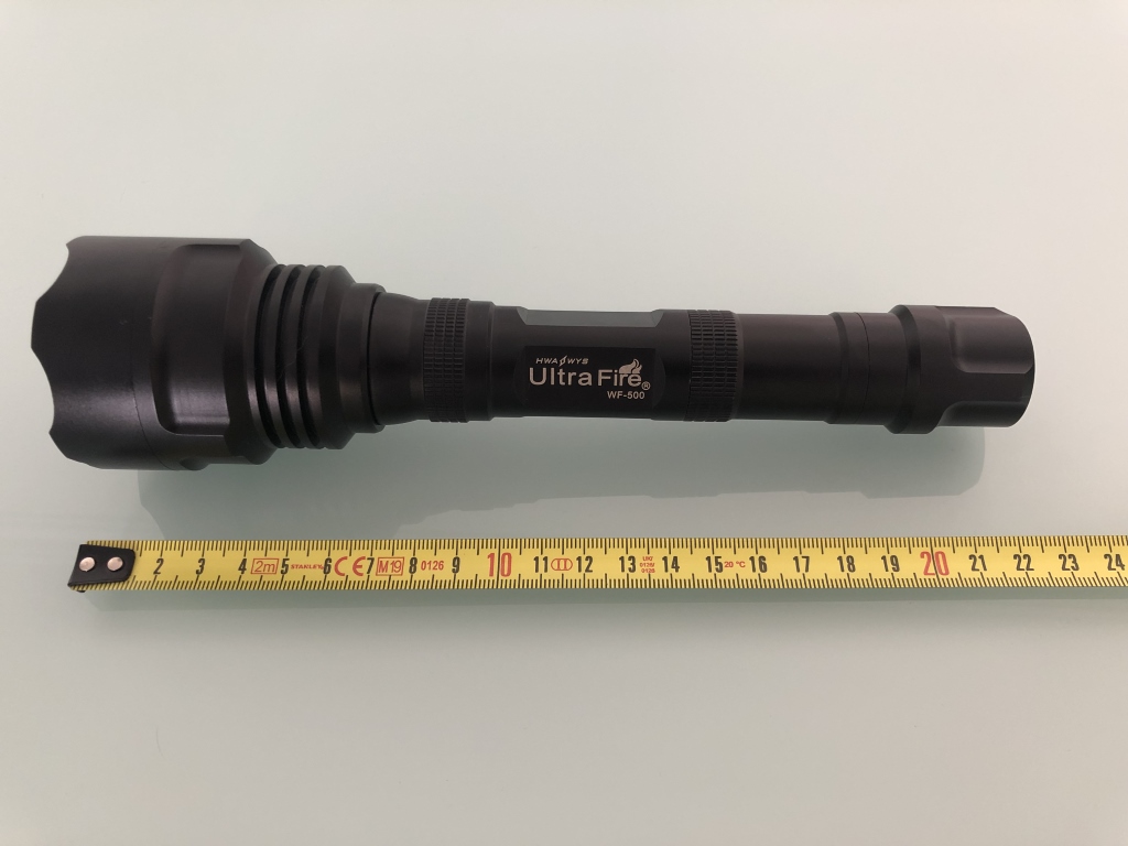
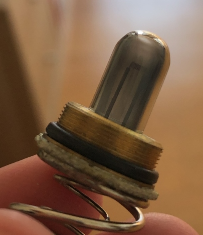
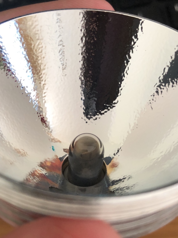
Some years ago, before LEDs were a thing, I bought an Ultrafire WF-500 Flashlight that features a Xeon light bulb. As you might imagine the bulb reached its lifetime and burned away.
Now a replacement bulb is available here https://www.ebay.com/itm/321916301663 the thing is that it will cost me 35€ and for that price I could just buy a new LED flashlight.
Now I was considering trying to adapt a generic LED bulb like this one here https://www.aliexpress.com/item/1005002419159094.html?mp=1.
Anyone else with this model of flashlight succeed at a similar mod? Any LED bulb recommendations? Or... is there any other source for the original bulb at a lower cost?
Some photos:
- https://cdn.tcb13.com/2023/wf500-bulb.jpg
- https://cdn.tcb13.com/2023/wf500-bulb2.jpg
- https://cdn.tcb13.com/2023/wf500-bulb3.jpg
Thank you.
179
9
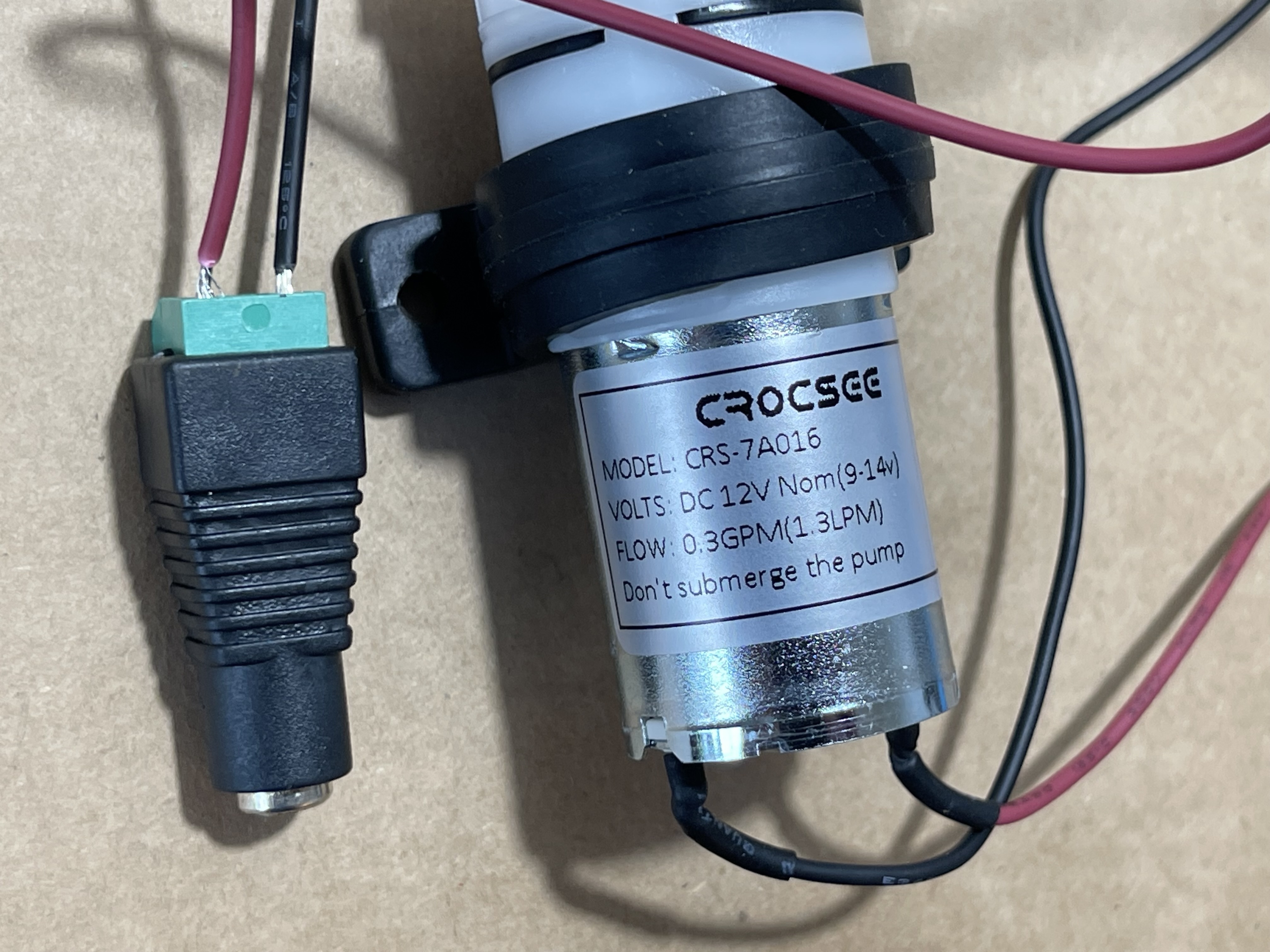
Looking for some Guidance Finding a Power Supply for a CrocSee CRS-7A016 Micro Water Pump (specs in post).
(reddthat.com)
Hi all, I have a water pump connected to an adapter (pictured) but I am having trouble getting it to run using any of the cords I had on hand; it calls for using DC-only & 12V (between 9-14). I have tried Googling around & browsing Amazon but I'm a bit overwhelmed with options. Can anyone suggest an adapter that'll get this little guy pumping? Please forgive my naivety & TIA.
Also, I hope that it's kosher I ask here. If it's not, please let me know if there's a better place. Thanks again.
180
I am powering a 5V microcontroller (arduino clone, atmega328p) using a 9V block and a buck converter. Now I want to let the microcontroller occasionally measure the battery voltage, so I can get an idea of how full it is.
My first idea was to use a simple voltage divider:
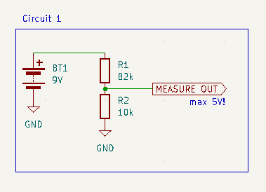
I've chosen the resistor values so that:
- the voltage at the measure output is
< 1.1V, to be able to use the 1.1V internal reference of the atmega's ADC R1 || R2 < 10kΩ, since the atmega datasheet says "The ADC is optimized for analog signals with an output impedance of approximately 10 kΩ or less"
This is great and all, but what bothers me is that this circuit will constantly draw ~100µA from the battery.
So, my next thought was to add a mosfet to the divider, to switch it on only while measuring:
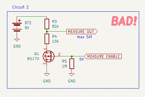
This is obviously bad, because now when the mosfet is off, the ADC input sees the whole battery voltage.
To address that issue, I've added a second mosfet into the measure path:
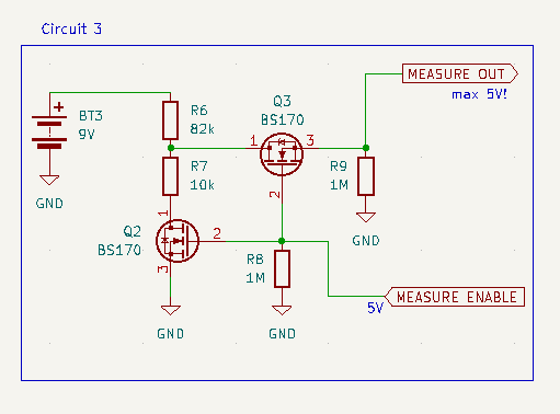
This works, and it does not draw any current, except while measuring.
However, it's quite a few parts. So I'm curious if anyone has an idea how to do this with just a single mosfet. It seems to me like it should be possible, but I haven't figured out how.
Oh, and if I'm doing something stupid here, please tell me :)
181
182
183
184
185
186
18
Does any one know about a this ad8445 /lm8445 ic it is supposed to be a timer ic but i am unable to find a data sheet for it
(lemmy.world)


187
188
189
Hi,
I'm looking for some help in a field that is super technical and I don't fully understand.
I'm planning on using a bunch of these seeed studio Esp modules for some home automation projects, especially because they have a lipo battery charger making it great for portable stuff.
The thing is the the ESP32s have U.FL SMD antenna connectors. Most of the antennas that you can buy with U.FL connections while are reasonably small, come with 50-150mm leads, which sort of makes the small size of the module a little less valid.
What I'd like to do is get a female U.FL SMD connector and make a small daugherboard with an 2.4GHz SMD antenna on it, for instance a Janson 2450AT42B100 or a Molex 479480001.
They go over the circuit board requirements quite thoroughly so I don't think designing it will be too difficult, but what I don't know is, they say that you need impedance matching on the circuit, and I see that there appears to be something that looks like it on the ESP circuit diagram, but I'm not actually sure if it is or not:
You can see it in the middle near the bottom of the diagram here: Seeeduino-XIAO-ESP32C3-SCH
So my questions are:
1: Is this a dumb idea, having a direct plug-on SMD antenna?
2: Is that an impedance matchning circuit between LNA_IN on the ESP chip and U.FL-R-SMT-1?
3: If I can't get a female U.FL SMD connector, would using one with a lead and shortening it to make the daughterboard able to be much closer to the connector affect anything? Do I need to ensure that the lead length matches the wavelength at all?
Edit: Found this SMD female U.FL, so they do exist.

190
I got my hands on an old e-ink price tag and want to repurpose this display.
Unfortunately, I can't really figure out, what this type of connector/bus is called. To me it looks like a standard issue ribbon cable.
There are some "universal" e-paper drivers (for example this one: https://www.ebay.de/itm/353141399922), but I have absolutely no idea, how to find out, if that's the right connector.
The device is made by Imagotag, if that helps.
Edit: I added a picture of the panel: https://feddit.de/pictrs/image/42ee4f60-231a-4c42-9a66-6c369134c49c.jpeg
None of the "markings" returned any results and the QR code couldn't be decoded by my phone.

191
Hi, I am automating my manual switches at home with ESPHome on NodeMCU. For controlling the switches, I am using 8 channel relay module.
The back of the board has solder-points sticking out. I will be installing this relay module inside the switchboard. So I want to put it in some kind of enclosure.
Just wanted to know your thoughts on enclosure. Should I just wrap the whole thing in electrical tape? Or a plastic box maybe?

192
193
194
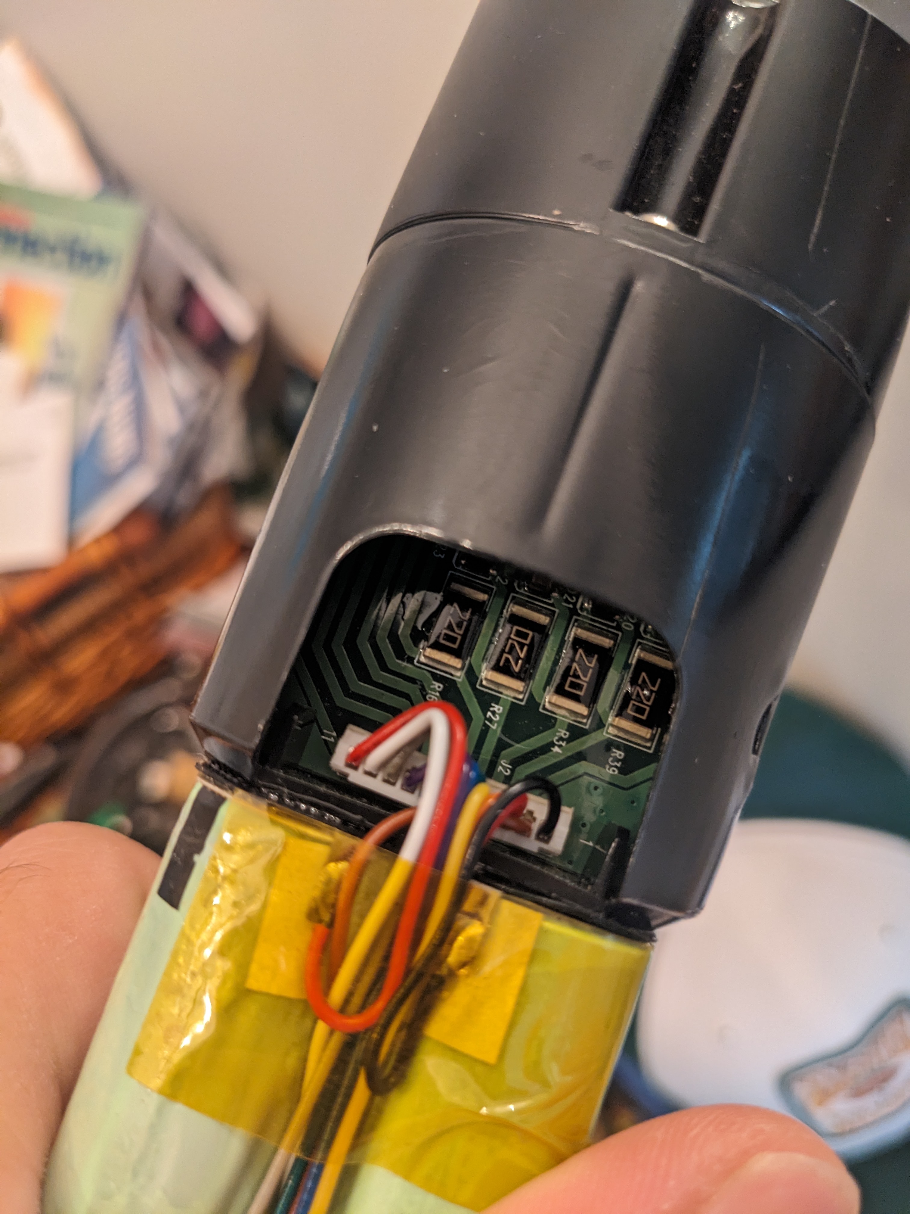
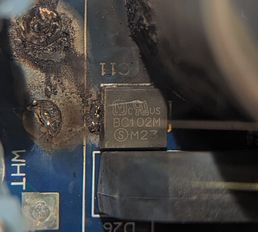
I purchased an e-bike which was advertised as just needing the batteries replaced. The li-ion batteries had been sitting dead for months. Once I got the battery removed it was clear that was not the case. You can see the hole where the plastic melted from this component overheating on the board. The burnt one is the same as those in the center of this photo.
What is it and how do I determine the correct replacement?
195
Trying to identify a component on a pool control board.
It's related to the T-Cell functionality of the board, since everything else like sensing, timing, and whatever else works on the board.
Component got water on it, most likely when a not uncommon occurrence of water jetting out from the filter and splashing onto the board eventually got where it shouldn't.
196
197
198
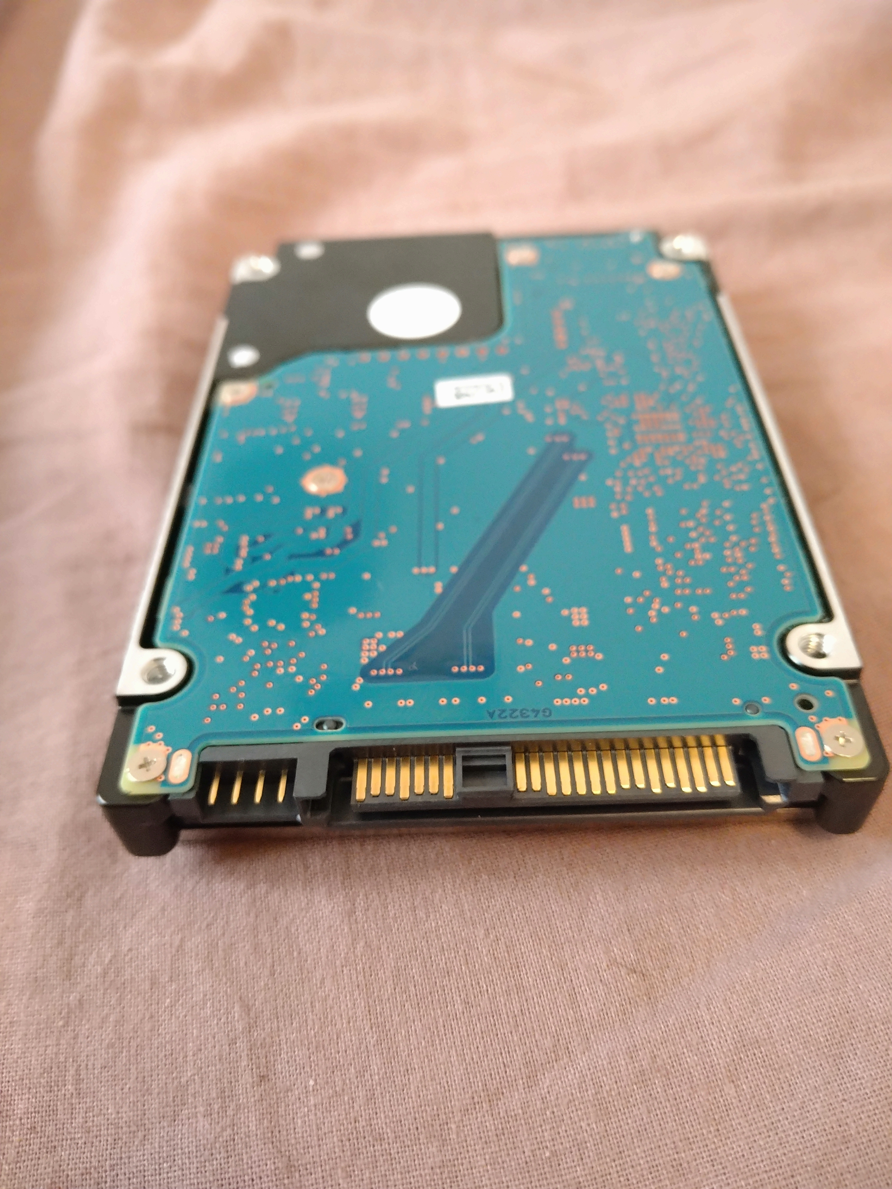
//Edit: It's a SAS drive. thanks for the help :))
I bought two of these a long time ago, and I recently tried to connect them to a SATA III connector without luck. The size seems to match up, but the block between the two pin segments seems to block it from connecting with SATA III.
Can you help me figure out what kind of adaptor I need ? :))
199
200